Instrumentation Systems & Services MicroSpeed 196 Скачать руководство пользователя страница 8

VII.

PROGRAMMING 

JOG MODE

When the Jog function is initiated and held, the MicroSpeed  196 will accelerate to
the speed programmed in Variable 06. Variable 29 enables you to follow the accel/
decel times (Variables 07 and 08) or to bypass the ramp times.

Variable 06 

-

 Jog Speed in User Units 

-

 Enter the desired jog speed in user units,

then press ENTER.

Variable 29 - Jog Ramp Selection - This variable allows the operator to select the
following jog ramp profiles:

0000 = No Ramp Time
0001 = Ramp on Decel
0010 = Ramp on Accel

0011 = Ramp on Accel and Decel

PROGRAMMING 

OPERATIONAL VARIABLES

Variable 07 - Acceleration Time 

-

 When the acceleration time is accessed, the alpha-

numeric display will read AcelTime. Enter the time in seconds desired for acceleration
from 0V (motor stop) to maximum output. The smallest unit of time is l/10 second.

Variable 06 - Deceleration Time 

-

 When the deceleration time is accessed, the alpha-

numeric display will read DcelTime. Enter the time in seconds for deceleration from

maximum output to 0V (motor stop). The smallest unit of time is l/10 second,

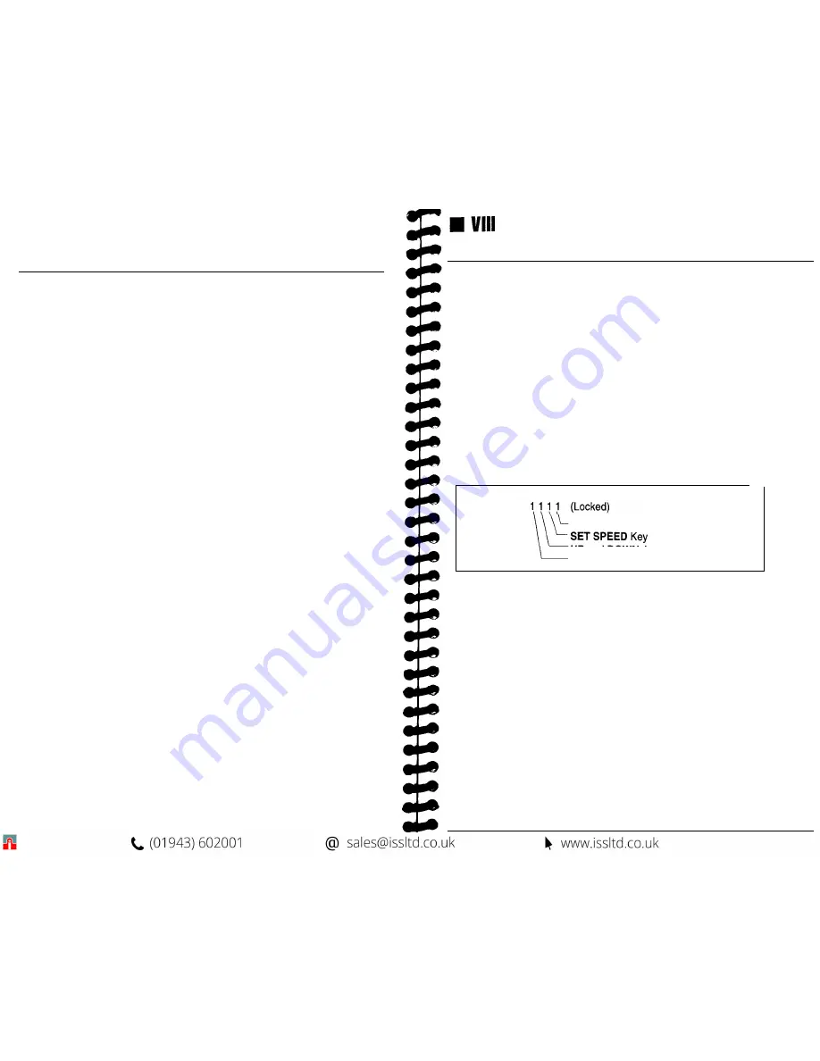
Variable 11 - Keypad Lockout 

-

 When Variable 11 is accessed, the alpha-numeric

display will read Key Lock. Each zero represents a different section of the keypad that
can be independently “locked.” The section of the keypad that is locked is determined by
placing a 1 (one) in the appropriate location. Any section or combination of sections can
be locked. (See chart below for lockout positions and descriptions.) After all program-
ming and tuning is complete, activate the lock out by installing a jumper on TB1-12 to

TBl-11.

Note: It is recommended that you “lock out” your variables, so that the MicroSpeed  196

cannot be inadvertently reprogrammed.

Positions: 0 0 0 0 (Unlocked)

VAR key and 2nd Func Key

Up and Down Arrows
Run, stop and jog Keys

DISPLAY:

Variable 21 - Display Selection -

 This Variable allows the user to select the

information that will be displayed on the Numeric display. Mode 0000 is commonly used
in normal operation, while modes 0001 through 0007 are typically used during setup or
troubleshooting only. When Variable 21 is selected, the alphanumeric display will read

Display#. 

To


select the numeric display mode during operation, enter a number from the

following list:

0000 =

 Tachometer in User Units

0001

 = Feedback Frequency in Hertz or Kilohertz

0002

 = Lead Frequency in Hertz or Kilohertz (Follower)

0003

 = Auxiliary Frequency in Hertz (Auxiliary Mode)

0004

 = Follower Error in Number of Pulses

0005

 = Total Output in DAC Bits (0 to 4094)

0006

 = Output Error in DAC Bits (-999 to 4094)

0007

 = Alarms (a “1” Indicates the Alarm Is Active)

1000

 = Zero Speed

0100

 = High Alarm

0010

 = Low Alarm

0001

  = Deviation Alarm

Содержание MicroSpeed 196

Страница 1: ...MSMAN32C MicroSpeed 196...

Страница 2: ...is designed in sequential order from basics to the highest level of MicroSpeed 196 programming The deeper you read into each section the less relevent the options may be to your application If this is...

Страница 3: ...d to the wiper of the speed potentiometer The isolated common terminal on the MicroSpeed 196 is connected to reference common on the drive Terminal locations are as follows TB2 2 Isolated Command Outp...

Страница 4: ...ignal from a PLC The MicroSpeed 196 only reads this input while stopped in the Ready mode Wiring of the Master Follower input is as follows TB1 15 Master Follower to common Open Master Closed Follower...

Страница 5: ...puts relays LEDs etc Power to the output circuits should be wired parallel with the Diode Protect TB2 20 terminal if inductive loads are driven to avoid damage to the output circuitry See Diagram 5 Wi...

Страница 6: ...display will prompt for a variable number and the numeric display will indicate two zeros 00 which will reflect the variable number entered Enter the desired variable number and press ENTER If you are...

Страница 7: ...FOLLOWER MODE The Microspeed 196 in the Follower mode mirrors a lead frequency input and can be scaled by the Ratio Set Point The lead frequency is typically generated from a digital transducer on ano...

Страница 8: ...can be independently locked The section of the keypad that is locked is determined by placing a 1 one in the appropriate location Any section or combination of sections can be locked See chart below...

Страница 9: ...ART MIN 56 PARTSIHR 57 Percent 58 RATIO 65 Customized 15 Diagnostic 0 Custom User Unit Labels If the choices presented in Variable 10 do not provide the display that is needed a Custom User Unit Label...

Страница 10: ...ect the proper polarity of the Command Output Voltage using the Forward Reverse Input Open Positive Closed Negative 3 Access Diagnostic 9 Digital Potentiometer by pressing 2nd Function key then the 9...

Страница 11: ...ters at the unstable speed 19 FOLLOWER MODE PID CONSIDERATIONS Variable 09 Max Lead Wind Up If you are speed matching and have very fast master speed changes or if you are bringing the Follower motor...

Страница 12: ...ill decrease motor speed Variable 28 Auxiliary Input Delay Delays the start of the Auxiliary Trim function on startup Enter the number of 10 msec update cycles to wait When ENTER is pressed the MicroS...

Страница 13: ...g inputs Closed Open Loop Master Follower Forward Reverse Keypad Unlocked Locked out Set Point 1 3 2 4 Set Point 3 4 Disabled Set Point 3 4 Enabled No Scroll Scroll Down No Scroll Scroll Up Left to ri...

Страница 14: ...oSpeed 196 with node address 01 will be the only MicroSpeed 196 to answer the host computer but all MicroSpeed 196 s will respond to global commands Never duplicate an address on the same communicatio...

Страница 15: ...ommunication Valid characters from the host are 0 command 1 read variable or 2 write variable The MicroSpeed 196 will echo the host in this character location unless the host communication message has...

Страница 16: ...in a message it will respond with a 3 in the Character 4 position The type of error will be specified in the Character 6 position Error type Problem 1 Parity Error Standard Definition 2 Data Error Da...

Страница 17: ...aximum Speed PPR Maximum Lead RPM Lead PPR User Unity Ratio Master Follower The active set point will only change with a Change Set Point command A write command to the active set point while running...

Страница 18: ...mp Compete Zero Speed Deviation Drive Enable Operational Specifications Accuracy Respons Modes of Operation Preset Speeds Accel Decel Times Processor Speed Display Alphanumeric Display Function LEDs D...

Страница 19: ......

Отзывы: