


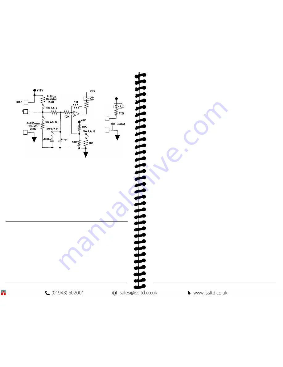
Diagram 4
Sensor Inputs, Switch Inputs:
Sensor Input
Switch Input
l
TB1-2,3,4
10K
TB1-5
+12V
2.2K
Sensor Connections -
The MicroSpeed 196 can accept: NPN Open Collecter,
3-wire (factory standard configuration); PNP Open Collecter, 3-wire; Magnetic pick-up,
2-wire; and Logic Level inputs. All sensors should have shielded cable with no unused
conductors.
The supply terminal (+12 Vdc unregulated) when using powered sensors (NPN or PNP)
for
Feedback, Lead,
or
Auxiliary
signals is terminal
TB1-1.
The common terminal for all sensor connections is terminal
TB1-5.
The
Feedback Signal
input is terminal
TB1-2.
The
Lead Signal
input is terminal
TB1-3.
The
Auxiliary Signal
input is terminal
TB1-4.
Note: When sharing signals, never use more than one pull-up resistor. See Diagram 4
for switch locations. See table below for sensor configurations.
Table 1
SENSOR SWITCH SETTINGS
Feedback Sensor
Lead Signal
12 11 10 9
Auxiliary Input
8 7 6 5 4 3 2 1
NPN Open Collector
OFF OFF OFF ON OFF OFF OFF ON OFF OFF OFF ON
PNP Open Collector
OFF OFF ON OFF
OFF OFF ON OFF OFF OFF ON OFF
Zero Crossing
ON ON ON
OFF
ON ON ON OFF ON ON ON OFF
Logic Level
OFF OFF OFF OFF
OFF OFF OFF OFF OFF OFF OFF OFF
NPN Open Collector; 2.2K
pull-up to
+12v,
trigger point at
2.5V
PNP
Open Collector; 2.2K
pull-down to common, trigger point at 2.5V
Zero Crossing (Mag);
100mV minimum peak, trigger point at 50mV
Logic Level;
trigger point at 2.5V
5
EXTERNAL CONTROL INPUTS:
The external control inputs give the operator control over the operating parameters of
the MicroSpeed 196. These parameters include:
Master/Follower
modes;
Keypad
Lockout; Forward/Reverse
(positive or negative voltage output);
Closed/Open
Loop
modes; and Local/Remote.
Note: All external control inputs should be Sustained, Normally Open switches, or
hardwired.
Master/Follower
-
This input tells the MicroSpeed 196 to operate independently (as
a Master), or to follow the lead signal of another device (feedback from a lead motor
or a generated signal from a PLC). The MicroSpeed 196 only reads this input while
stopped in the Ready mode. Wiring of the
Master/Follower
input is as follows:
TB1-15 (Master/Follower)
to common (Open =
Master;
Closed =
Follower).
Keypad Lockout
-
This input disables selected entries from the front panel keypad of
the MicroSpeed 196, as defined by programming the
Keypad Lockout Selection
variable. Use of this function is highly recommended Wiring of the
Keypad
Lockout
input is as follows:
TB1-12 (Keypad Lockout)
to common (Open=Keypad
Avail
able; Closed=Key
pad Lockout).
Forward/Reverse
-
This controls the voltage polarity of the
Isolated Command
Output. Forward
is a positive voltage.
Reverse
is a negative voltage. The polarity
will change immediately when the switch is closed or opened. Wiring of the
Forward/
Reverse
input is as follows:
TB1-13 (Forward/Reverse)
to common (Open=
Forward;
Closed =
Reverse).
Closed/Open Loop
-
This enables or disables the PID control. In Open Loop mode,
the feedback is ignored, so control is extended to providing a particular command
output voltage only, with no correction to maintain a set point. Wiring of the
Closed/
Open
Loop
input is as follows:
TB1-18 (Closed/Open
LOOP)
to common
(Open =
Closed Loop,
Closed =
Open Loop).
Local/Remote
-
This input controls the point of information entry to the MicroSpeed
196. In Local mode, commands for all functions and programming are taken from the
front panel keypad and terminal strip. In Remote mode, all programming and speed
commands must come over the RS-422 link. (Refer to “Section XII, the
Serial
Communications”
for more information.) Wiring of the
Local/Remote
switch is as
follows:
TB1-10 (Local/Remote)
to common (Open=
Local;
Closed =
Remote).
SETPOINT CONTROL INPUTS:
There
are eight set points that can be programmed into memory (four master Speed Set
Points, and four follower Ratio Set Points). These eight set points allow the operator to
use different speeds upon start-up, and to alter speed by toggling from one set point to
another. The speed change will follow the ramp profile programmed for
Accel
and
Decel.
Two switches control which programmed set point is active. The two inputs are:
Set Point 3 & 4 Enable,
and
Set Point 1(3)/Set Point 2(4).
6
Содержание MicroSpeed 196
Страница 1: ...MSMAN32C MicroSpeed 196...
Страница 19: ......


