


Active Set Point
Set Point 1(3)1Set Point 2(4)
Set Point 3 & 4 Enable
Set Point 1
Open
Set Point 2
Closed
Open
Set Point
3
Open
Open
Set Point 4
Closed
Closed
Closed
Set Point 3 & 4 Enable
-
Wiring of the
Set Point 3 &4 Enable
input is as follows:
TB1-9 (Set Point 3 & 4 Enable)
to common (Open = Set Points 1 & 2 Enabled;
Closed = Set Points 3 & 4 Enabled).
Set Point 1(3)/Set Point 2(4)
-
Wiring of the
Set Point 1(3)/Set Point 2(4) input
is as follows:
TB1-16 (Set Point 1(3)/Set Point 2(4))
t o common (Open = Set Point
l(3); Closed = Set Point
2(4)).
Scroll Up/Scroll Down -
These inputs are used to make small changes to the active
set point while running. The high and low alarm outputs can be tied to these inputs,
preventing operators from running too fast or too slow. N.O.
Momentary
contacts
should be used when wiring the
Scroll Up/ScrollDown
inputs. The terminals are:
Scroll Up = TB1-6; Scroll Down = TB1-8.
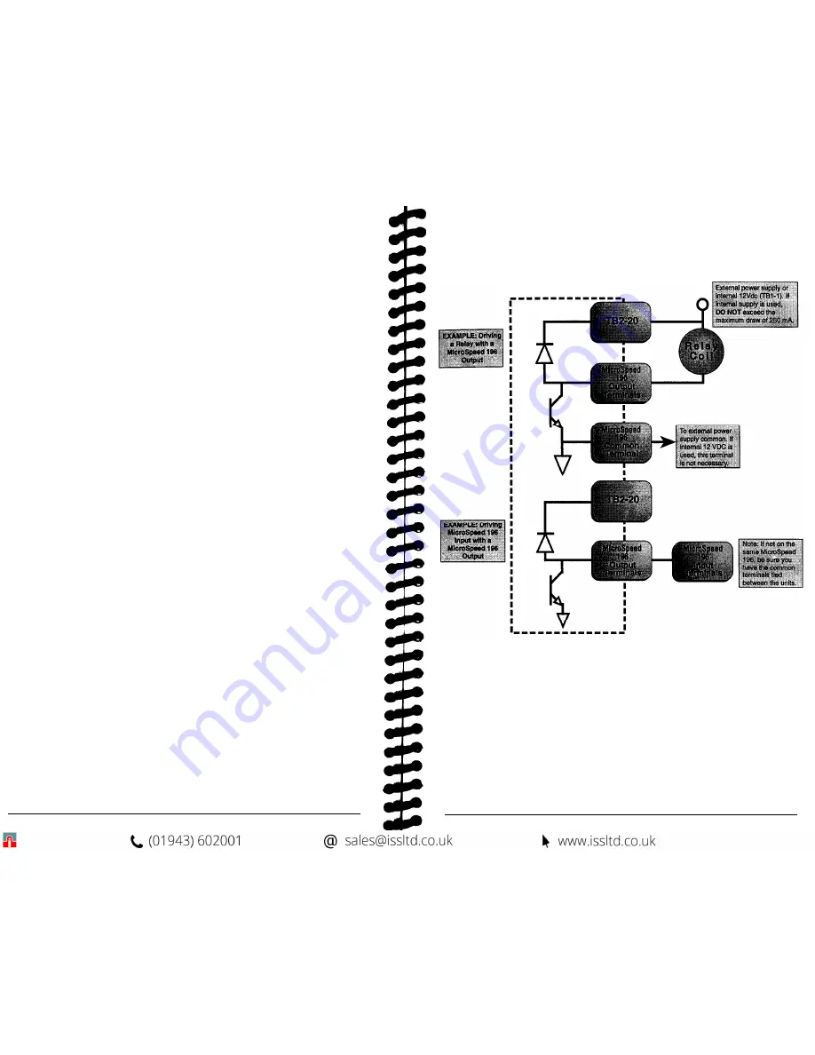
WIRING STATUS AND ALARM OUTPUTS:
The status and alarm outputs provide a completed circuit when a programmed result
occurs. (See
“Status and Alarm Outputs”
in Section VIII,
“Programming Operational
Variables”).
The outputs are Open Collector NPN transistors, rated for 5OVdc, 250mA
and .3-watt maximums.
These outputs are intended to be used with the Microspeed 196 inputs, relays, LEDs,
etc. Power to the output circuits should be wired parallel with the
Diode Protect
(TB2-20)
t erminal if inductive loads are driven, to avoid damage to the output
circuitry. (See Diagram 5: “Wiring Status and Alarm Outputs ”).
Diode Protect (TB2-20)
-
This is a protection circuit (back EMF diode). Input power
from the power supply should be wired in parallel with this terminal.
Drive Enable (TB2-16)
-
This output can be actuated under one of the three program-
mable conditions.
Drive Enable
is used to give the MicroSpeed 196 control over the
Run/Stop command on the drive, or on other MicroSpeed units.
L
OW
Alarm (TB2-19)
-
If the shaft speed drops below this programmed setting, the
output will conduct in order to actuate a load.
High Alarm (TB2-17)
-
If the shaft speed goes above this programmed setting, the
output will conduct in order to actuate a load.
Deviation Alarm (TB2-14)
-
This output is active in the Follower mode. If the
follower shaft is ahead or behind the Master exceeding the value programmed, the
output will actuate the load.
Ramp Complete (TB2-13)
-
This is a nonprogrammable output. This output is
actuated when the Speed Set Point selected is reached (Master mode only).
Zero Speed (TB2-11)
-
This is a nonprogrammable output. This output is actuated
when there is no feedback present, i.e., when the motor or shaft rotation has stopped,
or feedback is lost, due to an external problem.
7
Diagram 5
Wiring Status and Alarm Outputs:
8
Содержание MicroSpeed 196
Страница 1: ...MSMAN32C MicroSpeed 196...
Страница 19: ......


