Instrumentation Systems & Services MicroSpeed 196 Скачать руководство пользователя страница 6

IV.

PROGRAMMING 

GENERAL

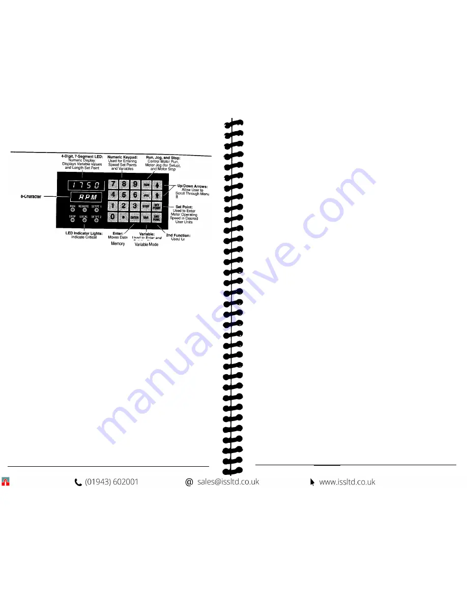
Alphanumeric Display:

Displays Current Operating

Mode or Identifies the Variable

Being Programmed

ems and Set Points

Operating Information Entries into Exit the

ENTERING AND ALTERING SET POINTS :


Change


Diagnostic  Tests

Set Point - The 

set 

point can be adjusted to any speed (or ratio) by pressing SET

POINT, 

entering a new speed using the number keys, and pressing 

ENTER. 

This

changes the programming of the current set point (Set Point 1,2,3,4  or Ratio 1,2,3,4).
The motor will immediately ramp to the new setting. If you wish to change a
non-selected set point, press 

SET POINT, 

then press the 

UP 

or 

DOWN 

arrows until the

desired set point is displayed, and enter the new set point.

Note: Decimal locations are fixed via programmable variables, and are not entered when
changing setpoints. The front panel LED displays will indicate which 

set

 poi

nt 

is active.

SET POINT =

    ACTIVE

LIGHTS ON SET POINT

1

1

2

2

1 & 2

3

NONE 4

Using the Arrow Keys to Alter Set Points 

-

 Minor adjustments to the set point

can be made by pressing the 

UP 

or 

DOWN 

arrows while the system is running. If an

UP or DOWN 

arrow key is pressed, the active set point will increase or decrease. The

rate of this change will increase if the key is held.

Programming THE VARIABLES:

The MicroSpeed  196 is programmed by entering data into a menu of variables. Only the
variables that affect operation of the unit as it relates to the application must be
programmed. Upon power up, the MicroSpeed 196 will display 

READY


on the alpha-

numeric display. This indicates that the MicroSpeed  196 is ready for operation or program-
ming. To program a variable, press 

VAR


on the front panel keypad. The alphanumeric

display will prompt for a variable number, and the numeric display will indicate two
zeros (00), which will reflect the variable number entered. Enter the desired variable
number and press 

ENTER

If you are unsure of the variable, the 

UP and DOWN

arrows 

on the keypad will allow you to scroll through the menu of variables. As you

9

scroll, the numeric display will indicate the number of the variable, and the alpha-
numeric display will name the variable. Press 

ENTER


when the desired variable is

displayed.

When the variable to be programmed is accessed, enter data using the numeric keys, and
then press 

ENTER.

Note: A decimalpointcannot lead an entry; the decimal placemust be preceded by a zero (0).

After


ENTER


is pressed, the display will ask for another variable number. If there is no

other variable data to be entered, press the 

VAR


key to return to the 

READY 

mode.

List of Variables:

Reference Variables - 

These variables tell the MicroSpeed 196 how to

control the motor, and can be changed in READY mode only:

01 Maximum RPM
02 User Units at Maximum RPM
03 Feedback Pulses per Revolution
04  Maximum Lead RPM (Follower)
05 Lead Pulses Per Revolution (Follower)
23 User Unity Ratio (Follower)

Operational Variables:

06 Jog Speed in User Units
07 Acceleration Time
08 Deceleration Time

10 User Unit Label
11 Keypad Lockout Selection

21 Display Selection
22 Follower Display Selection
29 Jog Ramp Selection

Control Loop Variables-

These variables tell the control how to correct for

speed errors:

09 Maximum Lead Wind-up (Follower)

12 Gain-P
13 Reset-l
14 Rate-D

Status and Alarm Outputs:

15 High Alarm
16 Low Alarm
17 Deviation Alarm (Follower)
18 Drive Enable

Auxiliary Mode Variables- 

Allows for a third frequency, i.e., dancer

systems, to trim the Follower mode ratio:

24 Auxiliary Mode Selection
25 Auxiliary Reference Frequency
26 Auxiliary Gain Percentage
27 Auxiliary Trim Selection
28 Auxiliary Input Delay

10

Содержание MicroSpeed 196

Страница 1: ...MSMAN32C MicroSpeed 196...

Страница 2: ...is designed in sequential order from basics to the highest level of MicroSpeed 196 programming The deeper you read into each section the less relevent the options may be to your application If this is...

Страница 3: ...d to the wiper of the speed potentiometer The isolated common terminal on the MicroSpeed 196 is connected to reference common on the drive Terminal locations are as follows TB2 2 Isolated Command Outp...

Страница 4: ...ignal from a PLC The MicroSpeed 196 only reads this input while stopped in the Ready mode Wiring of the Master Follower input is as follows TB1 15 Master Follower to common Open Master Closed Follower...

Страница 5: ...puts relays LEDs etc Power to the output circuits should be wired parallel with the Diode Protect TB2 20 terminal if inductive loads are driven to avoid damage to the output circuitry See Diagram 5 Wi...

Страница 6: ...display will prompt for a variable number and the numeric display will indicate two zeros 00 which will reflect the variable number entered Enter the desired variable number and press ENTER If you are...

Страница 7: ...FOLLOWER MODE The Microspeed 196 in the Follower mode mirrors a lead frequency input and can be scaled by the Ratio Set Point The lead frequency is typically generated from a digital transducer on ano...

Страница 8: ...can be independently locked The section of the keypad that is locked is determined by placing a 1 one in the appropriate location Any section or combination of sections can be locked See chart below...

Страница 9: ...ART MIN 56 PARTSIHR 57 Percent 58 RATIO 65 Customized 15 Diagnostic 0 Custom User Unit Labels If the choices presented in Variable 10 do not provide the display that is needed a Custom User Unit Label...

Страница 10: ...ect the proper polarity of the Command Output Voltage using the Forward Reverse Input Open Positive Closed Negative 3 Access Diagnostic 9 Digital Potentiometer by pressing 2nd Function key then the 9...

Страница 11: ...ters at the unstable speed 19 FOLLOWER MODE PID CONSIDERATIONS Variable 09 Max Lead Wind Up If you are speed matching and have very fast master speed changes or if you are bringing the Follower motor...

Страница 12: ...ill decrease motor speed Variable 28 Auxiliary Input Delay Delays the start of the Auxiliary Trim function on startup Enter the number of 10 msec update cycles to wait When ENTER is pressed the MicroS...

Страница 13: ...g inputs Closed Open Loop Master Follower Forward Reverse Keypad Unlocked Locked out Set Point 1 3 2 4 Set Point 3 4 Disabled Set Point 3 4 Enabled No Scroll Scroll Down No Scroll Scroll Up Left to ri...

Страница 14: ...oSpeed 196 with node address 01 will be the only MicroSpeed 196 to answer the host computer but all MicroSpeed 196 s will respond to global commands Never duplicate an address on the same communicatio...

Страница 15: ...ommunication Valid characters from the host are 0 command 1 read variable or 2 write variable The MicroSpeed 196 will echo the host in this character location unless the host communication message has...

Страница 16: ...in a message it will respond with a 3 in the Character 4 position The type of error will be specified in the Character 6 position Error type Problem 1 Parity Error Standard Definition 2 Data Error Da...

Страница 17: ...aximum Speed PPR Maximum Lead RPM Lead PPR User Unity Ratio Master Follower The active set point will only change with a Change Set Point command A write command to the active set point while running...

Страница 18: ...mp Compete Zero Speed Deviation Drive Enable Operational Specifications Accuracy Respons Modes of Operation Preset Speeds Accel Decel Times Processor Speed Display Alphanumeric Display Function LEDs D...

Страница 19: ......

Отзывы: