background image


15 

C.


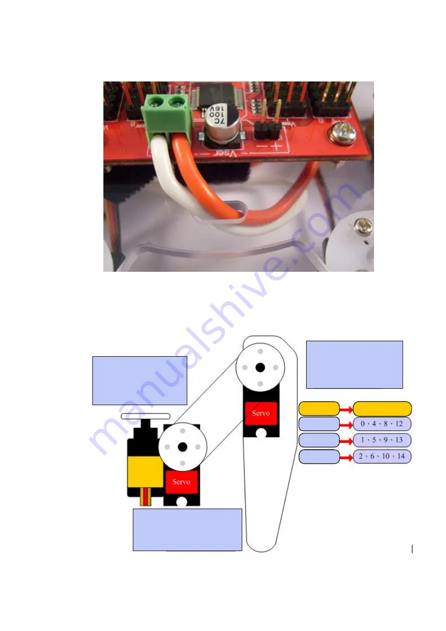
Pass the red and white wires upward through the hole and then fix them into 
the power input terminals with the screws. 
While installing, please pay attention to the polarity. The red wire should be 
connected to the “+” terminal and the white wire should be connected to the 
“-” terminal. 


Step 10: Install Servo Wires to Servo Commander 32 

Connect the control lines of each servo to the corresponding pins on Servo 
Commander 32. Please note whether the module IDs and servo IDs defined in the 
program agree with the module IDs and servo IDs on the Servo Commander 32 to be 
connected. The pin assignments for wire connection are as follows.   


[Configuration of the IDs of the joints] 

Inner joint: This servo is 
connected to the pins with 
smaller ID number, e.g., 
the position 0 in case of 
0-2. 

Outer joint: This servo is 
connected to the pins with 
larger ID number, e.g., the 
position 2 in case of 0-2. 

Joint part 

Servo ID 

Inner joint 

Middle joint 

Outer joint 

Middle joint: This servo is 
connected to the pins with 
intermediate ID number, e.g., 
the position 1 in case of 0-2. 

Содержание Mini Hexapodinno 18-DOF

Страница 1: ...Mini Hexapodinno 18 DOF Robot Instruction Manual Version 1 11 ...

Страница 2: ...e loss of equipment the loss of human safety and health and the loss of profit and reputation The product of the company shall not be used in life saving or any related instrument and equipment Children under 14 shall not use this product for any related experiment without being accompanied by adults Errata We hope the users may regard this document as a lively and practical instruction manual We ...

Страница 3: ...make sure the power supply or battery connecting to Servo Commander 32 is capable of providing 10A of current so as to properly operate the kit Insufficient current may cause unexpected results and damage of the kit When using a battery power supply to the module the voltage may lower after some while of operation and cause abnormal actions of the kit In such case remove and fully charge the batte...

Страница 4: ...g Leg Plate 6 The supporting leg is made of PC material and connects servo terminal with screws Sonar Support small 1 PC plate for module installation and connecting the sonar module Sonar Back Plate 1 PC plate for connecting the sonar module and the servo Servo 18 Servo provides for 180 rotation movements capable of simulating articulation behaviors connections with signal power and ground are re...

Страница 5: ...can measure the distance of 2cm 5m by emitting and receiving the sound waves It can communicate with Servo Commander32 through cmdBUS Power Line with Switch 1 Used for connecting the battery and the module boards for switching the power on off Velcro Cable Strap 1 It is attached on the module installation board for fixing the power supply battery Double sided Tape 1 Used for attaching and fixing s...

Страница 6: ...they do not tangle or affect motions unexpectedly during the operation of the servo 1 Tools Phillips Screwdriver 2mm and 3 mm Long Nose Pliers Screw Glue selectively used at the joint between nut and Aluminum Plate to prevent the nut from loosening ...

Страница 7: ...is within the safe range While installing please pay attention that the left and right leg plates should be assembled in different orientations Each side has three leg plates Screw A Nut Power supply input terminals Please pay attention to the polarity of the power supply It is necessary to connect the terminal to the positive electrode of the power supply and connect the terminal to the GND elect...

Страница 8: ...kshop iv Click the Tool item in the menu bar on the top v Click the Motion Editor in the pull down menu If a warning window appears it means that the BASIC Commander is not correctly connected Please check if the USB line is connected or unplugged and then plug it in again to ensure a correct connection Exit the Motion Editor and then re click this button Click the application in the innoBASIC Wor...

Страница 9: ...vos on the left side to move all the servos to their central points Please note that the number next to it should be 1500 If it is not 1500 please click the number directly enter the number 1500 and then click Enter Check if all servos are at the correct positions Please maintain the servo at the same angle before the disk is fastened during the assembly In case the disk is moved please follow thi...

Страница 10: ... disk is moved please follow this adjustment procedure again to prevent from any unexpected movement or damage to the parts Screws for servo disks provided with the servo While assembling pay attention that all the larger side of the center hole on the installation plate face down as shown in the above figure While assembling please note that the curved edge should face outward Screw B ...

Страница 11: ...ce down as shown in the above figure While assembling the curved edge should face outward Screw B While assembling please pay attention to the positions for installing the left and right servos and module installation board as shown in the left figure While assembling please pay attention to the direction The circular hole should face forward Screw B ...

Страница 12: ...y attention that the positions marked with arrows should be aligned point to point and the two servos should be placed perpendicular to each other While assembling please pay attention that the circular hole faces forward and the PC board of all the legs faces forward Double sided Tape ...

Страница 13: ...he strap upward through Point A on the Module Installation Board and then pass it downward through Point B Note The two ends of the cable strap under the Module Installation Board should be balanced in length as shown in the above figure Screw C Nut While installing please pay attention that I O connecting pins are located here ...

Страница 14: ...13 While installing please check if the Velcro cable strap has been installed Screw C Plastic Post A ...

Страница 15: ...with Switch Nut A Washer B Washer C and Nut D B Assemble them in the sequences of Nut A Washer B Module Installation Board Power Line with Switch as describe above Note While installing Washer B please pay attention that the protruded part on Washer B should be hooked into the small hole on the Module Installation Board as shown in the following figure ...

Страница 16: ...ease note whether the module IDs and servo IDs defined in the program agree with the module IDs and servo IDs on the Servo Commander 32 to be connected The pin assignments for wire connection are as follows Configuration of the IDs of the joints Inner joint This servo is connected to the pins with smaller ID number e g the position 0 in case of 0 2 Outer joint This servo is connected to the pins w...

Страница 17: ...ssignments Note The corresponding servo IDs are printed on Servo Commander 32 Pay attention that the orange white wire is the signal line the red wire is the power line and the brown black wire is the ground wire Please connect these wires to the corresponding positions marked on the module to avoid damage to the module and then arrange the wires orderly as shown in the following figure Module ID ...

Страница 18: ...on to adjust the ID of the sonar module to 3 according to Note 1 Double sided Tape After the installation is completed connect the wires of the head servo to Pin 3 of Module 0 on Servo Commander32 and then connect the cmdBUS While installing please pay attention to the polarity as shown in the right figure ...

Страница 19: ...the power supply Please make sure that the voltage and current from the power supply are within the range required by the servo After connecting the power line the servo will make a transient motion after receiving the switch surge which is normal While connecting the power cord please pay attention not to place your hands within the space where the servo will move into to avoid being clamped 3 St...

Страница 20: ...w will appear Please make sure that the fine tuning of the mechanical parts has been performed successfully After confirming all the mechanical parts are correctly assembled and tuned please click OK If Cancel is clicked the Motion Editor will be terminated If the mechanical part is not correctly assembled at this moment please click Cancel to terminate the program Click Motion Editor to start the...

Страница 21: ... move all the servos to their central points Please note that the number next to each checkbox should be 1500 If it is not 1500 please click the number directly enter the number 1500 and then click Enter 9 Click the Set Fine Tune Values button at the upper right corner 10 If the fine tune values are not yet stored the Filename will be unnamed The user can specify a preferred name while storing the...

Страница 22: ...can perform the adjustment described in Step 4 again 12 Please write down the values after the fine tune Click Save File select the location for storing the file enter a preferred filename and then click OK to save the values in the PC The left right arrow buttons can be used to rotate the servo clockwise or counterclockwise Please observe the rotation of the servo to the required central position...

Страница 23: ...xit button at the lower right corner to close the fine tune operation Please enter a preferred name in the filename and then click Save Click the Close button to close the window After the file is successfully stored the filename of the last stored file will be displayed in the Filename Click the Exit button to close the Motion Editor ...

Страница 24: ...opy the folder Mini 6 Legged Robot Documents to the PC 2 In the innoBASIC Workshop click Tool in the menu bar on the top 3 Click Motion Editor in the pull down menu 4 Click the button Set the Corresponding Motion at the bottom of the Motion Editor ...

Страница 25: ...0 frm below the motion files on the left side click the Frame0 under the Module0 and Module1 and then click the button 8 Make sure that the frame0 under the Module0 and Module1 has become The selected folder will be highlighted Please make sure that the selected folder is Mini 6 Legged Robot Frame Before clicking the button to download the motion file into the module please make sure that the Fram...

Страница 26: ... the Motion File and Frame1 under the Module0 and Module1 as the two steps describe above Repeat the operation for all the motions until Frames 0 12 have been downloaded to the corresponding frames After the download is complete the original text frame0 will turn into Mini 6 Legged Robot Demonstrative Motion0 ...

Страница 27: ... under the Module0 and Module1 have been changed to the corresponding motions 11 After the verifying the operations click the Close Window button at the lower right corner to close the window for setting the corresponding motions Please make sure that first 13 Frames have been successfully downloaded ...

Страница 28: ...27 12 In the Edit Servo Motions window click the Exit button at the lower right corner to close the Motion Editor 13 Click File in the menu bar and click Open File ...

Страница 29: ... be highlighted Please make sure that the selected folder is Mini 6 Legged Robot Forward Movement Demonstration Program or Mini 6 Legged Robot Forward Movement Demonstration Program Click the Open button to download the program into the innoBASIC Workshop for editing or creating motions The number on the left side represents the line number of the program The Function starts at Sub and ends at End...

Страница 30: ...PosOffset command has two parameters one is the Servo ID and the other is the fine tune value Please enter the fine tune value according to the value recorded for each servo ID The number in the figure is arbitrarily defined Please do not enter the same number as shown in the figure If the user is not sure about the function of each button the user can move the mouse pointer over the image After a...

Отзывы: