


EAGLE
mGuard
I15007_en_02
Innominate Security Technologies
241
Signal contact
The signal contact monitors the EAGLE
mGuard and thus enables remote diagnostics. In-
terruption of the contact via the floating signal contact (relay contact, closed current circuit)
indicates the following:
–
Failure of at least one of the two supply voltages.
–
Permanent error in the EAGLE
mGuard
(internal
3.3
V
DC
voltage,
supply
voltage
1
or
2 < 9.6 V, etc.).
–
A faulty link status of at least one port. The link status message for each port can be
masked on the EAGLE
mGuard via the management software.
By default upon delivery, there is no connection monitoring.
–
Error during selftest.
If the supply voltage is not redundant, the EAGLE
mGuard
indicates
the
failure
of
the
supply
voltage. This message can be prevented by feeding the supply voltage via both inputs.
Ground connection
•
To ground the EAGLE
mGuard, a separate screw connection is available.
Serial port
The serial port (serial interface) can be used as follows:
To configure the mGuard
via the serial interface. There are two options:
–
A PC is connected directly to the serial interface of the mGuard (via the serial interface
of the PC). The PC user can then use a terminal program to configure the mGuard via
the command line.
–
Or a modem is connected to the serial interface of the mGuard. This modem is connect-
ed to the telephone network (fixed-line or GSM network). The user of a remote PC,
which is also connected to the telephone network by a modem, can then establish a
PPP (Point-to-Point Protocol) dial-up connection to the mGuard and configure it via a
web browser.
To manage data traffic
via the serial interface instead of via the WAN interface of the
mGuard. In this case, a modem should be connected to the serial interface.
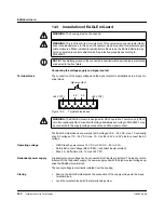
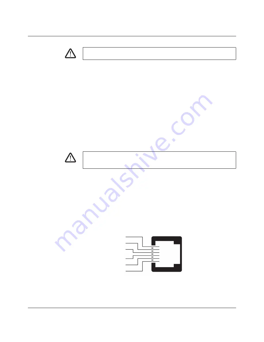
Figure
13-4
Pin assignment of the RJ12 socket (serial port)
WARNING:
Only PELV circuits or optionally SELV circuits with voltage limitations accord-
ing to EN 60950-1 may be connected to the signal contact.
WARNING:
The serial interface (RJ12 socket) must not be connected directly to the tele-
communications connections. To connect a serial terminal or a modem, use a serial cable
with RJ12 plug. The maximum cable length of the serial cable is 30
m.
Pin 6
Pin 5
Pin 4
Pin 3
Pin 2
Pin 1
Not used
CTS
TXD
RTS
RXD
GND
RJ12
Содержание mGuard
Страница 6: ...Innominate Security Technologies...
Страница 32: ...mGuard rs4000 rs2000 32 Innominate Security Technologies I15007_en_02...
Страница 74: ...mGuard rs4000 rs2000 3G 74 Innominate Security Technologies I15007_en_02...
Страница 108: ...mGuard pci SD 108 Innominate Security Technologies I15007_en_02...
Страница 142: ...mGuard centerport 142 Innominate Security Technologies I15007_en_02...
Страница 156: ...mGuard delta 156 Innominate Security Technologies I15007_en_02...
Страница 180: ...mGuard pci 180 Innominate Security Technologies I15007_en_02...
Страница 196: ...mGuard blade 196 Innominate Security Technologies I15007_en_02...
Страница 236: ...mGuard industrial rs 236 Innominate Security Technologies I15007_en_02...
Страница 254: ...EAGLE mGuard 254 Innominate Security Technologies I15007_en_02...
Страница 260: ...Assigning IP addresses and setting up DHCP TFTP servers 260 Innominate Security Technologies I15007_en_02...


