5.10 Connection to the PV array
The cables connecting the equipment to the PV array access the unit through
the PG cable glands located on the cabinet sides or base.
Prior to any manipulation, always check to ensure there is no electrical
hazard at the PV array voltage input.
Never forget that any incident light on the panels generates voltage
at the panel terminals.
Therefore the inverter interior may hold voltages of up to 600 volts
even when not connected to the Grid.
The use of safety gloves and glasses homologued for electrical risk is
compulsory to ensure lack of voltage.
Caution:
Connect the positive pole of the string of panels to the terminals mar-
ked , and the negative pole to the terminals marked .
If the distance between the inverter and the PV array connection point
requires the use of a greater cable section, then the use of an external
distribution box, located close to the inverter, is compulsory in order to
change from one section to another.
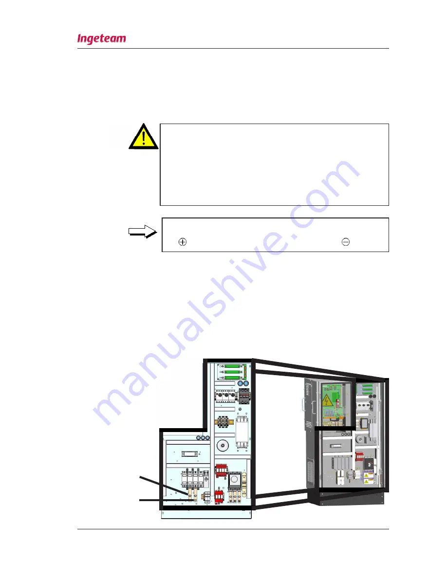
In following pictures the plates or terminals of each model are shown:
INGECON
SUN 15 U 208V and INGECON
SUN 15 U 480V.
This units are equiped with two terminal, one for each pole, for wires with
a maximum section AWG 2.
DC plate
+
DC plate
-
Installation and Operation Manual
INGECON
®
SUN SMART U
AAS2000IKI05
AAS2000IKI05
Rev. _
Date: February 2011
Page 46


