


51
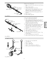
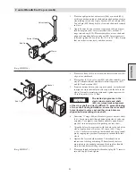
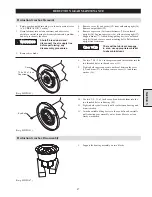
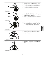
1.
Place planet gear (39) on the cardboard square and insert pin
tool.
2.
Insert 5 to 7 needle bearings (41) into gear around pin tool,
ensure first few needle bearings do not tip over.
3.
Insert spacer (59) followed by all 24 needle bearings.
(Dwg. MHP1164)
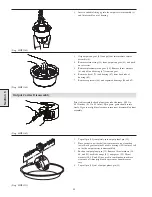
4.
Place a thrush washer (either 34,40 or 42) on top of this
followed by another cardboard square.
5.
Pinching both cardboard squares, flip assembly over. Finish
inserting the remaining needle bearings.
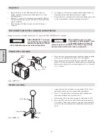
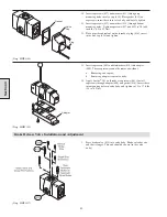
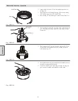
6.
Place another thrust washer on top of assembly. Carefully slide
assembly right into the output carrier (37).
(Dwg. MHP1161)
7.
Align the bores and push out the pin tool using the output
planet pin (35). Measure the side clearance and adjust the
thrust washers (34, 40, or 42) to provide 0.005 - 0.032 inches
(0.13 - 0.81 mm). Spin gears, gears should rotate freely.
(Dwg. MHP1169)
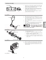
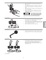
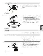
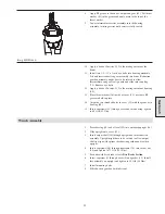
8.
Measure the distance that roll pin (38) must be tapped into
carrier so that the roll pin is half in the carrier and half in the
pin, and mark the punch.
(Dwg. MHP1165)
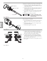
9.
Tap roll pin (38) into output carrier (37) to the mark on the
punch.
(Dwg. MHP1166)
Section 5
Punch
Содержание FA5A
Страница 10: ...10 DISC BRAKE PARTS DRAWING Dwg MHP0667 Dwg MHP0630 One Way Clutch Detail Section 1...
Страница 19: ...19 Section 2 SERVICE NOTES...
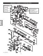
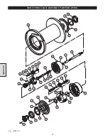
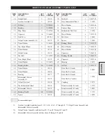
Страница 54: ...54 REDUCTION GEAR ASSEMBLY PARTS DRAWING Dwg MHP1221 Section 5...
Страница 57: ...57 SERVICE NOTES...
Страница 58: ...58 SERVICE NOTES...
Страница 59: ...59 SERVICE NOTES...


