

41
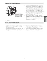
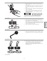
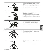
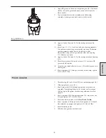
Control Handle End Cap Assembly
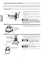
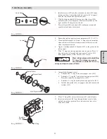
1.
Place the split portion of valve clevis (446) over shaft (401),
with large portion on top of shaft and rounded portion of valve
clevis facing valve body. Apply Loctite
®
609 on roll pin (409).
Tap roll pin (409) through valve clevis and shaft until centered
in clevis.
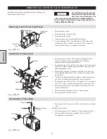
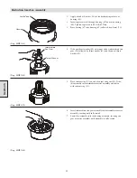
2.
Apply Loctite
®
680 on threads of capscrews (465) and insert
into detent plate (464). Insert cross shaft (461) without ‘O’
rings into end cap (450). Place detent plate on cross shaft and
align with mounting holes in end cap (450). Insert capscrews
(465) and tighten to 42 to 45 in. lbs. (15.5 to 16.7 Nm). Ensure
that cross shaft rotates freely and then remove.
(Dwg. MHP1156)
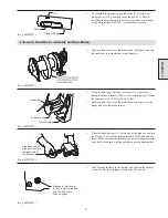
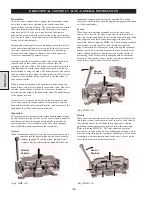
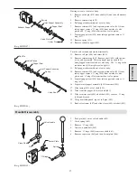
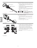
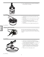
3.
Place valve body (410) on its side with the clevis end over the
edge of the workbench.
4.
Place gasket (411) on valve cap (450) and slide assembly over
clevis. Lubricate threads and loosely install capscrews (437)
and (439) and washers (433).
5.
From the bottom hole in valve cap use a punch, or similar tool,
to align the cross shaft holes in valve cap with the hole in the
clevis. Use tool to maintain position and tighten capscrews to
54 to 60 inch lbs (20 to 22 Nm).
NOTICE
The slotted pin grooves in the
clevis (where clevis and shaft
(401) are joined) make alignment
of the cross shaft and clevis difficult. To prevent binding
of cross shaft during installation, ensure the cross shaft
holes (located in valve cap) and the clevis hhole are
aligned before installing cross shaft.
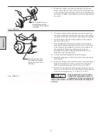
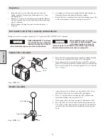
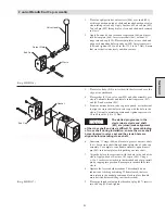
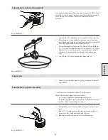
6.
Lubricate ‘O’ rings (448) and locate in grooves on cross shaft
(461). Insert cross shaft through detent plate side of valve cap
assembly. To complete, raise handle assembly up and insert
pin (463) into detent plate while pushing on cross shaft.
7.
Align the hole in the cross shaft with the hole in the end of the
clevis. Apply a bead of Loctite
®
242 to pin (445). Using a
8-32 x 2 inch screw attached to the threaded end of pin, install
pin by tapping into position. Ensure pin is inserted fully into
clevis.
8.
Operate the lever in both directions. There should be no
indication of sticking or binding. When released, the lever
must return to the neutral position and lock in place (handle
must be lifted before shifting in either direction).
(Dwg. MHP1157)
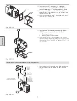
9.
Place pipe thread sealant on the threads of plug (447), insert it
into end cap (450) and tighten.
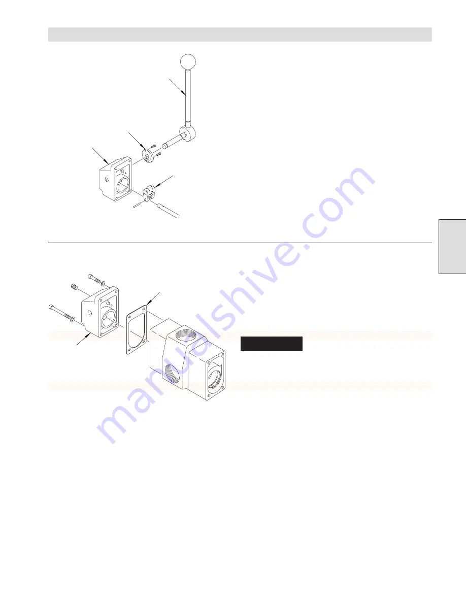
Section 4
Clevis
Detent Plate
End Cap
Valve Handle
Gasket
End Cap
Содержание FA5A
Страница 10: ...10 DISC BRAKE PARTS DRAWING Dwg MHP0667 Dwg MHP0630 One Way Clutch Detail Section 1...
Страница 19: ...19 Section 2 SERVICE NOTES...
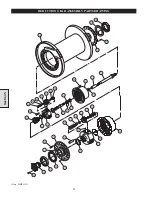
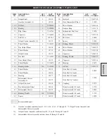
Страница 54: ...54 REDUCTION GEAR ASSEMBLY PARTS DRAWING Dwg MHP1221 Section 5...
Страница 57: ...57 SERVICE NOTES...
Страница 58: ...58 SERVICE NOTES...
Страница 59: ...59 SERVICE NOTES...


