


31
Section 3
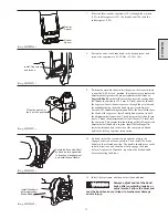
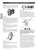
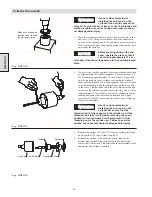
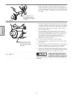
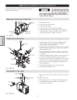
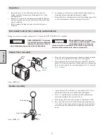
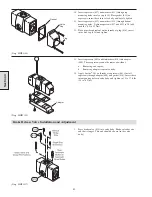
Adjusting the Automatic Band Brake
1.
Thread a piece of 3/8 NC rod all the way into the cylinder rod.
With the brake band slack and no air applied to the band brake,
push the end of the threaded rod to position the plunger all the
way inside the bracket. Turn a nut down the threaded rod until
it is even with or just touching the cylinder cover. Apply air
pressure to the band brake cylinder from an outside air source.
When air pressure is applied to the cylinder, the nut on the
threaded rod should move about 25 mm (1 inch) away from the
cover. Tighten the adjustment nut to remove slack from the
brake, and remove the air pressure from the cylinder. When
you remove the air pressure, the nut should move closer to the
cylinder end cover and then stop.
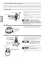
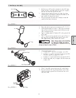
2.
Repeat the process of applying air, adjusting, and removing air
until the nut stops (when there is no air applied to the brake) at
approximately 14 mm (9/16 inch) from the cylinder cover.
Tighten the jam nuts closest to the plunger to fasten the
adjustment bolt in position. Finally, remove the 3/8 NC
threaded rod from the cylinder rod.
(Dwg. MHP0983)
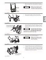
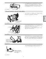
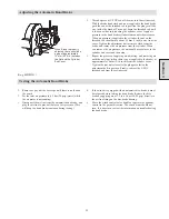
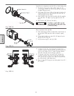
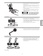
Testing the Automatic Band Brake
1.
Remove or pay out the wire rope until there is no load on
the winch.
2.
Set the inlet air pressure to 6.3 bar (90 psig) static (while
the air motor is not running).
3.
Disconnect the air line from the automatic band brake, and
plug the air line to prevent the loss of air pressure. (This
will keep the band brake tensioned during testing.)
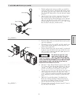
4.
If the winch is equipped with an automatic disc brake, it must
be released before testing the band brake. Release the disc
brake by applying air at 3.5 to 6.3 bar (50-90 psig) directly to
the air line fitting on the disc brake housing.
5.
Move the winch control valve handle or operate the pendant
control in the payout direction. The winch drum should not
turn. If it does turn, review the information on troubleshooting
the band brake.
When Brake is properly
adjusted, there should be
a gap of approximately
14 mm (9/16 in.) between
the Nut and the Cylinder
End Cover.
Содержание FA5A
Страница 10: ...10 DISC BRAKE PARTS DRAWING Dwg MHP0667 Dwg MHP0630 One Way Clutch Detail Section 1...
Страница 19: ...19 Section 2 SERVICE NOTES...
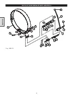
Страница 54: ...54 REDUCTION GEAR ASSEMBLY PARTS DRAWING Dwg MHP1221 Section 5...
Страница 57: ...57 SERVICE NOTES...
Страница 58: ...58 SERVICE NOTES...
Страница 59: ...59 SERVICE NOTES...


