


36
DIRECTIONAL CONTROL VALVE MAINTENANCE
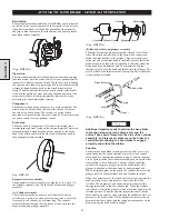
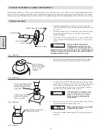
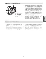
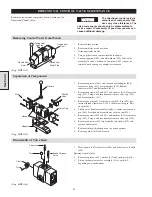
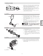
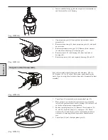
Removing Control Valve from Winch
1.
Remove brake air line.
2.
Remove muffler or exhaust hose.
3.
Disconnect inlet air line.
4.
Using a pipe wrench, remove inlet hose adapter.
5.
Loosen capscrews (442) and flatwashers (434). Take valve
assembly to clean work bench. Capscrews (442) cannot be
removed until end caps or adapter are removed.
(Dwg. MHP1121)
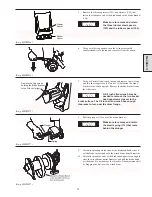
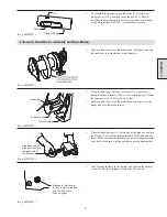
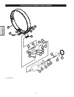
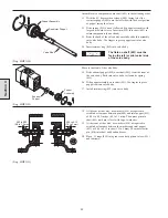
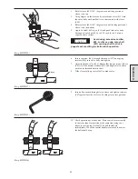
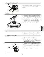
Separation of Components
1.
Remove capscrews (441) and separate valve adapter (440)
from valve body (410), discard gasket (424). Remove
capscrews (442) and flatwashers (434).
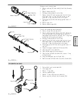
2.
Remove capcrews (439 and 437) and washers (433) from valve
cap (438). Using a soft face hammer remove valve cap (438)
and discard gasket (411).
3.
Remove the plug (447) from valve cap (450). Pin (445) has
internal threads. Install an 8-32 x 2 inch screw into pin. Pull
out pin (445).
4.
Lift up valve handle assembly slightly, to remove pressure on
pin (463). Press handle assembly out of valve cap (450).
5.
Remove capcrews (439 and 437) and washers (433) from valve
cap (450). Using a soft face hammer remove valve cap (450).
6.
Remove capscrews (418) from shuttle valve body (479) and
remove shuttle valve.
7.
Remove fittings (this depends on the winch options).
8.
Remove gasket (419) and discard.
(Dwg. MHP1145)
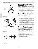
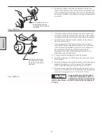
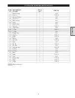
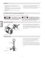
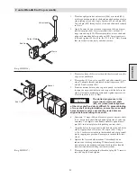
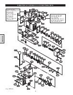
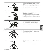
Disassembly of Valve Body
1.
Press out pin (409) from clevis (446) and slide clevis off shaft
(401).
Entering from air inlet.
2.
Remove capscrew (465), washer (417) and spring clip (416).
3.
Lift out brake release valve assembly (413) or pin (412)
depending on winch options.
(Dwg. MHP1146)
Section 4
Read these instructions completely before working on the
Directional Control Valve.
NOTICE
The directional control valve is
comprised of components that
have very close tolerances. The
valve components should only be disassembled to
make a repair. Disassembly of good components can
cause additional damage.
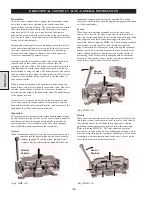
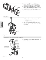
Viewed from
Left Side
Viewed from
Front
Viewed from
Right Side
Viewed from
Rear
Handle
Shuttle
Valve
Plug
Gasket
Adapter
Valve Cap
Capscrew
Pin
Brake Release
Valve
Clevis
Pin
Содержание FA5A
Страница 10: ...10 DISC BRAKE PARTS DRAWING Dwg MHP0667 Dwg MHP0630 One Way Clutch Detail Section 1...
Страница 19: ...19 Section 2 SERVICE NOTES...
Страница 54: ...54 REDUCTION GEAR ASSEMBLY PARTS DRAWING Dwg MHP1221 Section 5...
Страница 57: ...57 SERVICE NOTES...
Страница 58: ...58 SERVICE NOTES...
Страница 59: ...59 SERVICE NOTES...


