


48
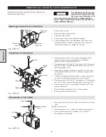
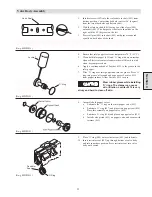
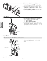
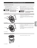
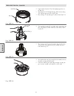
2.
Insert a suitable lifting jig into the output carrier assembly (3)
and lift assembly out of housing.
(Dwg. MHP1168)
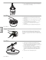
3.
Grip output sun gear (45) and pull out intermediate carrier
assembly (4).
4.
Remove retainer ring (53) from output sun gear (45) and push
out of carrier.
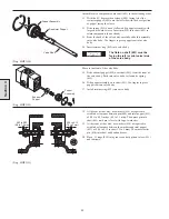
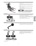
5.
Remove intermediate sun gear (54). Remove thrust washers
(63 and 65) and bearing (67) from sun gear.
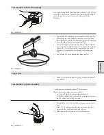
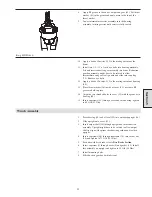
6.
Remove oil seal (71) and bearing (67) from back side of
housing (69)
7.
Remove capscrews (68) and separated housings (44 and 69).
(Dwg. MHP1160)
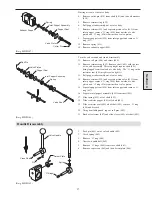
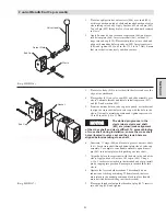
Output Carrier Disassembly
Prior to disassembly check planet gear side clearance, 0.005 to
0.032 inches (0.13 to 0.81 mm). Spin gears, gears should rotate
freely. If gears are tight or clearance is incorrect, disassemble planet
assembly.
(Dwg. MHP1169)
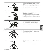
1.
Tap roll pin (38) completely into output planet pin (35).
2.
Place carrier in a wide shallow container or on a clean shop
towel. Each gear contains 42 needle bearings (41) that may fall
out as the output carrier is disassembled.
3.
Push out output planet pin (35). Remove thrust washers (34,
40, and 42), needle bearings (41), and spacer (59). Thrust
washers (34, 40, and 42) are used in combination to achieve
clearance, all three might not be present or quantities may
vary.
4.
Tap roll pin (38) out of output planet pin (35).
(Dwg. MHP1222)
Section 5
Содержание FA5A
Страница 10: ...10 DISC BRAKE PARTS DRAWING Dwg MHP0667 Dwg MHP0630 One Way Clutch Detail Section 1...
Страница 19: ...19 Section 2 SERVICE NOTES...
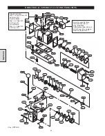
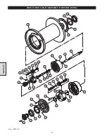
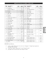
Страница 54: ...54 REDUCTION GEAR ASSEMBLY PARTS DRAWING Dwg MHP1221 Section 5...
Страница 57: ...57 SERVICE NOTES...
Страница 58: ...58 SERVICE NOTES...
Страница 59: ...59 SERVICE NOTES...


