User Manual V1.1a | XtracontrolEC22
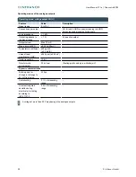
Data of the the digital inputs
Feature
Value
Description
Cable length
max. 30 m
For unshielded connection cables
Cables over 30 m in length must be shielded
Cable cross-section in
control cabinet
after voltage drop
▶
Only select after voltage drop (there are no
further practical restraints).
Field wiring
according to
regulations and
standards
▶
Comply with all local regulations and the
stipulations of EN 61131-2.
Rated load voltage
24 V DC (SELV)
–
Protection against
reverse polarity
yes
–
Potential isolation
no
–
Status display
yes
One orange LED per input
5.3.3
Counter inputs
From version 0200 on, the first 4 digital inputs of the XtracontrolEC22 (X3: I1…I4) may alternatively be used as
counter inputs (C1…C4).
Activating this function requires license, which can be obtained subsequently.
The counter inputs C1…C4 have fast filters, the unipolar inputs I5…I16 have hysteresis.
The counter inputs are connected to the signals of the other unipolar inputs. There is no changeover switching.
Available options for the counter inputs:
up-down counter
pulse and direction counter
quadrature decoder
One of the counter inputs may alternatively be used as a capture input. This configuration requires 3 inputs (partially
as CNT input or CAPT input).
The edges for up, down or pulse may be set to falling and/or rising edge.
Direction: high = up; low = down
Examples for counters: up/down; pulse/direction; encoder (A/B)
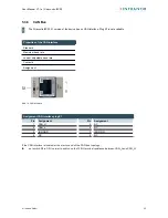
Abb. 7: counter up/down or pulse/direction
Pin
Designation
Pin
Designation
C1
Up, pulse, A (CNT0)
C3
Up, pulse, A (CNT1)
C2
Down, direction, B (CNT0)
C4
Down, direction, B (CNT1)
22
©
Infranor GmbH
Содержание XtracontrolEC22
Страница 1: ......
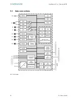
Страница 18: ...User Manual V1 1a XtracontrolEC22 5 3 Data connections Abb 4 block diagram 18 Infranor GmbH ...


