


SMT-BD2
2 - PUTTING INTO OPERATION
The "Enable" input must be open and the analog input command CV open or short-circuited (X4 connector can be
disconnected).
Test the auxiliary supply voltage :
Rated value = 230 Vrms single-phase.
Maximum value (must never be exceeded) = 260 Vrms, all mains variation tolerances included.
Switch on the auxillary supply. The green ON Led must be lit and the UNDERVOLT error must be displayed.
Test the power supply voltage :
- For the 220 VAC amplifier version:
Rated value = 230 Vrms between phases.
Maximum value (must never be exceeded) = 260 Vrms, all mains variation tolerances included.
- For the 400 VAC amplifier version:
Rated value = 400 Vrms between phases.
Maximum value (must never be exceeded) = 480 Vrms, all mains variation tolerances included.
Switch on the power supply. The UNDERVOLT error Leds must be unlit. The braking resistor must remain cold.
!
CAUTION ! This resistor is under high voltage
Check that the amplifiers front panel screws are correctly fastened on the rack.
3 - AMPLIFIER COMMISSIONING AND ADJUSTMENT
3.1
-
A
MPLIFIER SETUP
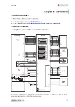
Connect the encoder feedback cable between the motor and the amplifier X1 connector.
Connect the X4 command connector : the Enable input must be open, the FC+ and FC- limit switches inputs must
be connected and closed, and the analog input command CV must be open or short-circuited.
Connect the serial link RS 232 between the PC and the amplifier X5 connector.
Switch on the PC and the monitor and then start the WINDOWS® interface.
Start the
Visual Drive Setup
software installation and follow the instructions.
Turn on the SMT-BD2 amplifier and start the
Visual Drive Setup
software.
If the message "
No serial communication found
" appears on the screen, click on
OK
and check following points
before connecting again the
Visual Drive Setup
software:
- the amplifier is on (green LED
ON
must be lit),
- the amplifier and the PC are correctly connected via the RS 232 link,
- the software configuration (
Com. port and Baudrate
) is correct.
The
Connect
and
Disconnect
commands in the
Setup
menu allow to change the serial link connection from one
amplifier to the other without leaving the
Visual Drive Setup
software.
!
The amplifier command cables (input command, serial link, encoder, HES) as well as the power
cables must be connected and disconnected with the amplifier turned off.
38
Chapter 6 – Commissioning
Содержание SMT-BD2
Страница 1: ...SMT BD2 gb DIGITAL SERVO DRIVE FOR SINUSOIDAL BRUSHLESS AC MOTORS 1 SMT BD2 ...
Страница 2: ...SMT BD2 2 SMT BD2 ...
Страница 4: ...SMT BD2 4 SMT BD2 ...


