SMT-BD2
Chapter 5 - Adjustable functions
1 - HARDWARE ADJUSTMENTS
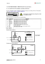
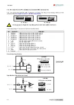
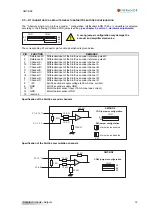
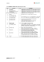
All the hardware adjustments of the SMT-BD2 amplifier module are presented on the following diagrams.
PSTH
A
B
C D
PR8
PR3
F2
F1
B3
B2
B1
X4
X2
X5
X1
1 2 3 4
ON
1 2 3 4
ON
MN
OP
COD
B2
B1
COM
B5
B4
B3
B
C
JK
KL
ZM
01656C
Current loops
(power board)
Firmware memory
16 bit ADC (option)
CT/BD2 (option)
Power fuse
(power board)
Only for the
220 V
AC
range
Logic fuse
(power board)
I/O
Inputs 0 V
reference
Motor thermal
sensor type
Encoder signal
Commutation signal
Serial link selection:
B=RS-232 (standard)
C=RS-422 (option)
Parameters
EEPROM
"Undervolt." fault
inhibition
Encoder marker pulse
disable/enable
Drive address selection
Motor thermal
sensor adjustment
+5 V supply
RS-422 (option)
For amplifier types 220/04 to 220/60 and 400/15 to 400/60 VAC range
30
Chapter 5 – Adjustable functions
Содержание SMT-BD2
Страница 1: ...SMT BD2 gb DIGITAL SERVO DRIVE FOR SINUSOIDAL BRUSHLESS AC MOTORS 1 SMT BD2 ...
Страница 2: ...SMT BD2 2 SMT BD2 ...
Страница 4: ...SMT BD2 4 SMT BD2 ...


