EonStor S12F-R1432/G1433 Installation and Hardware Reference Manual
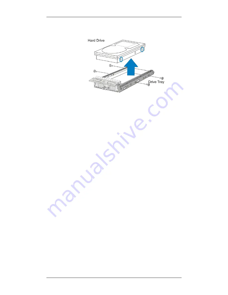
sides of the drive tray (two on each side). (See
the figure
below)
Figure 5-27: Removing the Hard Drive
Step 6.
Install the replacement drive.
Please refer to
Section
2.7
for the complete hard drive installation procedures.
Step 7.
Re-install the drive tray back to the subsystem.
Please refer to
Section 2.8
for detailed instructions.
Step 8. Check the drive tray LEDs.
The green power status
LED should light up, showing that power is supplied to
the disk drives. The Drive Busy LED should also start
flashing, indicating that system is attempting to access
the hard drive.
5.8
Replacing a MUX Kit
If a MUX kit is damaged or fails, often identified as drive-side signal
glitches, follow these instructions to replace it:
Step 1.
Remove the drive tray from the drive bay in the
subsystem
. (See
Section 5.7.2, step 1-4
)
Step 2.
Remove the hard drive from the drive tray
, after the
drive tray has been removed from the subsystem. (See
Section 5.7.2, step 5
)
Step 3.
Turn the drive tray over and
remove the two (2)
retention screws
that hold the old MUX kit in place.
(See the figure below)
5-22
Содержание EonStor S12F-G1433
Страница 34: ...EonStor S12F R1432 G1433 Installation and Hardware Reference Manual This page is intentionally left blank 1 20...
Страница 110: ...EonStor S12F R1432 G1433 Installation and Hardware Reference Manual This page is intentionally left blank 5 24...
Страница 124: ...EonStor S12F R1432 G1433 Installation and Hardware Reference Manual B 8 Power Connectors IEC type receptacle B 8...


