114 |
www.HandiQuilter.com
9.
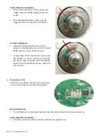
Adjust the sensor if necessary (if the LED is constantly on and will not turn off, the sensor is too close
to the tension discs. If it will not trigger on when the thread is pulled, the sensor should be adjusted
closer to the check spring).
10.
Reinstall the front panels. (See
To install the front plastic panels
in section 23,
Front Plastic Panels
.)
To remove the thread break sensor
1.
Remove the front plastic panels. (See
To remove the front plastic panels
in section 23,
Front Plastic
Panels
.)
2.
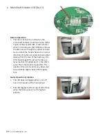
Loosen the thread break sensor set screw using a 2mm hex tool.
3.
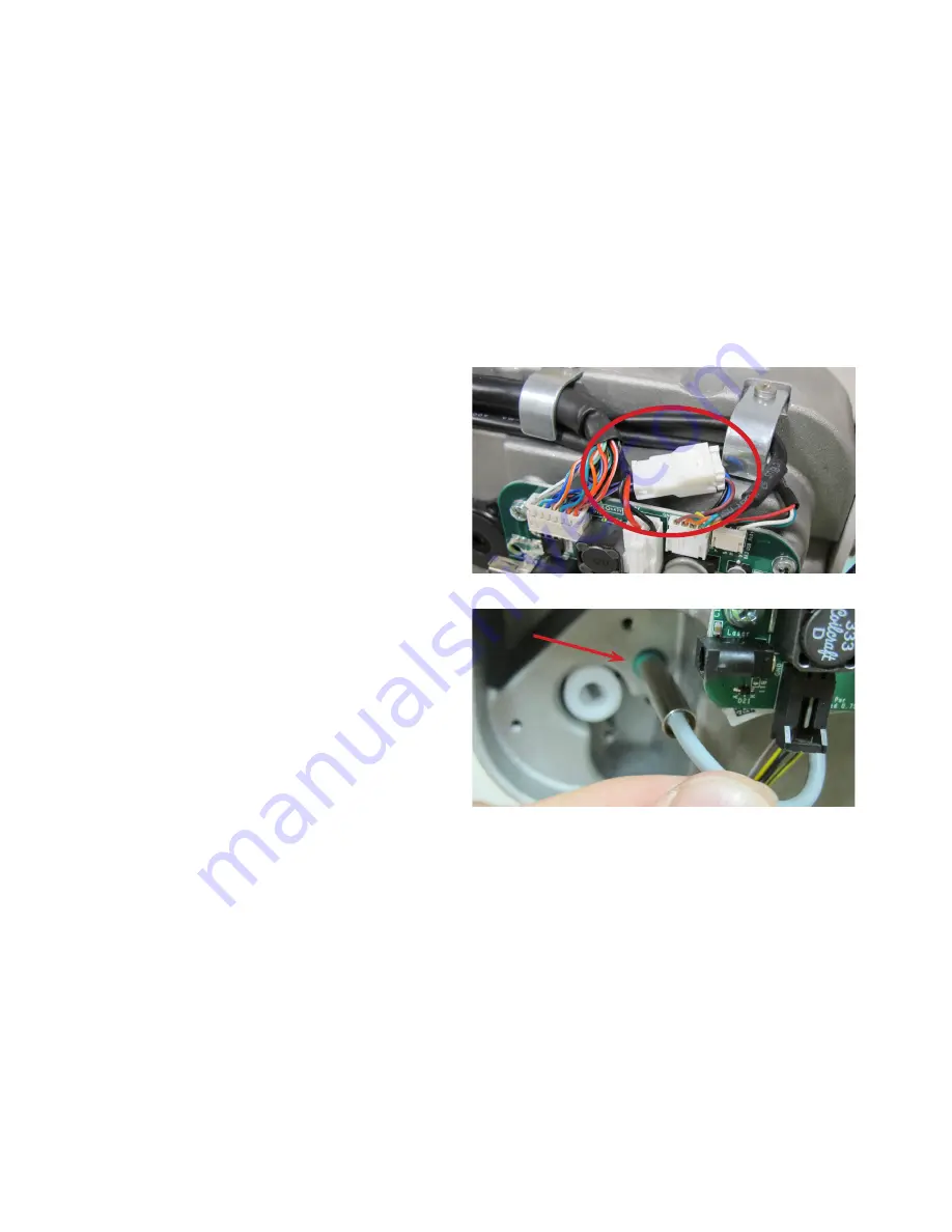
Disconnect the sensor cable at the top of the
head frame, just above the front distribution
board. The cable has a white 4-pin connector
with three wires attached.
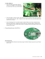
4. Pull the sensor out from the left-hand side of
the head frame by gently pulling on the sensor
cable. If necessary, use a small blunt tool (such
as a 2mm or 2.5mm hex tool) to gently push the
green end of the sensor on the right side of the
head frame while pulling on the gray cable on
the left side of the head frame and remove the
sensor from the head frame.
5.
Because the sensor cable is routed behind the front distribution board, it is necessary to remove the
four screws from the front distribution board with a #1 Phillips screwdriver to completely remove the
sensor.
To install the thread break sensor
1.
Plug the sensor cable into the 4-pin connector at the top of the head frame.
2.
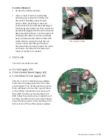
Route the sensor cable behind the front distribution board, being careful not to pinch any wires
between the board and screw standoffs.
3.
Reattach the front distribution board with a #1 Phillips screwdriver and the four Phillips screws.

