background image

12  | 

 www.HandiQuilter.com


Â

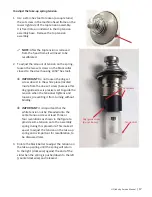
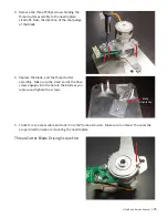
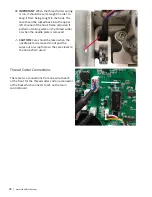
IMPORTANT

: The take-up lever caged 

needle bearings must be packed well using 

the special syringe (part number QM40241) 

at least every 15 million stitches. Lubricate 

the two places indicated in the previous 

image. 


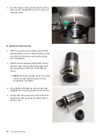
NOTE

: Use this grease on the counter 

weight needle bearing also.


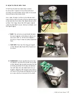
Hook Race

#6 Purple:

 Use Conoco Hydro clear R&O 32, or 

similar oil (e.g. Texaco 22 or Velocite 10). It is 

recommended that the hook race be oiled with 

every bobbin change and before quilting if the 

machine has been idle for more than a day.


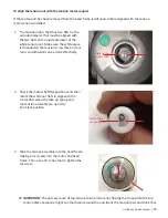
3. Thread Mast, Hand Wheel, and Thread Guides

The following observations, accompanied by necessary adjustments, will ensure trouble-free thread 

passage. Failure at any of these points will significantly affect thread tension.

Содержание QM40275

Страница 1: ... free Handi Quilter Inc assumes no responsibility or liability for any errors or inaccuracies that may appear in the informational content contained in this manual Handi Quilter HQ Infinity HQ Avanté HQ Fusion HQ Sixteen HQ Sweet Sixteen HQ Pro Stitcher and TruStitch are either trademarks or registered trademarks of Handi Quilter Inc Printed in the United States of America Part number QM40275 04 0...

Страница 2: ...des 12 Check Thread Mast 12 Check Hand Wheel Gap 13 Check Thread Guides and Stirrup 14 4 Top Thread Tension 14 Take up Spring Position 16 Take up Spring Tension 16 Components of the Tension Assembly 20 5 Thread Cutter 22 Thread Cutter Alerts 22 Components of the Thread Cutter 29 6 Securing Flats and Screws 30 First Screw First Position 30 Main Shaft 30 Pitman Short Shaft 31 Hook Shaft 32 Take up L...

Страница 3: ...elt Idlers Flanges 47 13 Presser Bar Height 48 14 Needle Position 50 Front to Back 50 Left to Right 51 15 Timing 53 Loop Lift and Hook to Needle Distance Timing 53 Tools Required 55 Correcting Loop Lift and Hook to Needle Distance Timing 60 Stop Finger 64 Needle Bar Height Timing 66 16 Power 71 Surge Protection Battery Backup 72 Fuse 72 17 Electrical Wiring 74 AC Wiring 74 18 Handlebar Switches 76...

Страница 4: ...r LED 101 Heartbeat LED 102 Test 3 LED 103 3 3 Volt Supply LED 103 5 Volt Control Board Supply LED 103 5 Volt Motor Driver Supply LED 103 26 LED Boards 104 ARM LED Board 104 Left and Right Handle LED Boards 104 Hook LED Board 105 Hook LED Cable 106 LED Ring 108 27 Thread Tension Sensor and Motor 109 Thread Break Tension Board 109 Thread Tension Motor 111 Thread Break Sensor 112 28 Needle Laser 115...

Страница 5: ...aphs and explanations that we hope will aid you in your repair efforts In addition to the teaching aids found herein you will also find all of the tools listed that are necessary for adjustments If you need help in locating these tools for purchase please contact Handi Quilter Notes Important Notes and Cautions NOTE A NOTE indicates important information that helps you make better use of your Hand...

Страница 6: ...e cases Electrostatic Discharge ESD Observe precautions for handling electrostatic sensitive devices whenever you are handling any of the circuit boards in the HQ Infinity These precautions include Whenever possible work performed on the quilting machine that includes handling any of the circuit boards should be done at an ESD safe work bench An ESD safe workbench should include An ESD safe mat co...

Страница 7: ...tich every two inches 2 and one stitch every four inches 4 Needle System 134MR Needle Size recommended 80 12 to 130 21 Hook System Rotary Horizontal M class bobbin Bobbin Type Aluminum Class M Bobbin Case Type MF Type MF adjustable anti backlash spring Motor Type Brushless DC with full servo control Needle Positioning Up and down walking stitch Electrical Power 100 240 VAC 50 60 Hz 600 watts peak ...

Страница 8: ...edle bearings on reciprocating counter weight cages bearings 5 Kluber GLY 151 Polylub Orange Reciprocating counterweight POM sleeve black plastic dampening grease if used instead of sintered bronze sleeve 6 Conoco Hydroclear R O 32 or similar white oil i e Texaco 22 or Velocite 10 Purple Hook race NOTE Other bearings in the machine are sealed bearings and do not require lubricating HQ Lubricant Pa...

Страница 9: ... and every 15 million stitches thereafter i e 30 million 45 million etc a pop up message appears to remind the owner to have the machine serviced Where to Lubricate Most bearings are sealed bearings on the Infinity machine However the following places need to be lubricated by the servicing technician Needle bar and presser bar sintered bronze bearings Use 1 Red Kluber Constant OY68 oil for top two...

Страница 10: ...d bronze Use 5 Orange Kluber GLY 151 Polylub dampening grease around the inside edge if the sleeve is black plastic POM Front two hook shaft sintered iron bearings Use 1 Red Kluber Constant OY68 oil for hook shaft front two sintered iron bearings Lubricate the two places indicated NOTE Photos of the bottom start with the machine on its side ...

Страница 11: ...ant for these two sintered iron bearings It should not be necessary to relubricate these two pockets when servicing the machine Take up lever articulating link and needle bar driver Use 3 Yellow Kluber GLY 2100 liquid grease on the articulating link the take up lever and the needle bar driver Lubricate the three places indicated Take up lever caged needle bearings Use 4 Green NCA 15 Isoflex grease...

Страница 12: ...ight needle bearing also Hook Race 6 Purple Use Conoco Hydro clear R O 32 or similar oil e g Texaco 22 or Velocite 10 It is recommended that the hook race be oiled with every bobbin change and before quilting if the machine has been idle for more than a day 3 Thread Mast Hand Wheel and Thread Guides The following observations accompanied by necessary adjustments will ensure trouble free thread pas...

Страница 13: ... the rear machine cover and the hand wheel NOTE The hand wheel screws are inside the rear machine covers and cannot be seen from the outside of the machine therefore the hand wheel can only be adjusted with a rear cover removed Check the gap here A correction is necessary only if the hand wheel is rubbing has an extreme gap or is loose To correct the hand wheel gap 1 Remove one of the front panels...

Страница 14: ...he three hold thread guide 2 and thread stirrup 3 NOTE The nut is on the inside of the front cover 4 Top Thread Tension   IMPORTANT Home sewing machines release the top tension whenever the presser foot is raised The HQ Infinity machine does not have any presser bar lever or top tension release mechanism Also the thread is wrapped around the bottom of the top tension assembly into the tension di...

Страница 15: ...cs apart preventing them from providing proper tension on the thread NOTE Tapping the minus button on the Easy Touch Tension screen changes the tension by one count per tap Pressing the handlebar minus button while the Easy Touch Tension screen is displayed changes the tension by two counts per press it does not continue to count up or down if the button is held down   IMPORTANT As long as the E...

Страница 16: ...e tension device If the tension is remove then it has to be recalibrated Calibration is covered later in this section 2 Rotate the tension assembly until the straight part of the spring is straight up make sure the tension device is seated into the head frame and retighten the set screw The hole is machined just deep enough for the back tension disc to not touch the frame Take up Spring Tension Ch...

Страница 17: ...d inside from the one set screw because this dog guide screw is precisely set to guide the tension when the tensioner tightens and loosens preventing it from turning without binding   IMPORTANT It is important that the white tension nut be threaded onto the center tension screw at least three or four revolutions as shown in the figure to provide some tension onto the assembly spring during this ...

Страница 18: ...the end of the center tension screw by turning it counterclockwise 2 Slide the barrel and black collar off the center tension screw Remove the black plastic take up spring tension holder out of the take up spring NOTE The larger shoulder covers the spring and the smaller diameter goes into the spring when reinstalled 3 Push lightly on the take up spring loop while wiggling until the spring pops ou...

Страница 19: ...ur turns so calibration can be done effectively 2 Check the motor shaft flat positions and then rotate the white nut flats to align with the motor flats when the take up spring and top tension assembly are up at the 12 o clock position 3 Slide the tension assembly into the head frame making sure it seats into the motor and head frame Then use a 2mm hex tool to tighten the set screw   IMPORTANT T...

Страница 20: ... tension assembly is removed or replaced 1 Touch the Tools button 1 in the toolbar Then touch the Calibrate Tension button 2 along the bottom of the screen 2 Touch the Tension button 3 in the center of the screen to begin calibration 3 The motor will loosen one turn to read its sensors It then tightens fully until it stops and then loosens four or five turns Lastly the system will set the tension ...

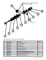
Страница 21: ...DED POINT 1 9 QM13089 HOLDER TU SPRING AUTO TENSNR 1 10 QM13083 NUT AUTO TENSIONER DM 1 11 QM13242 DISK MOD TENSION SPRING BASE 1 Bill of Materials Tension Assembly QM59104 Item Part Number Description Quantity 1 QM13088 Screw Auto Tensioner 1 2 QM13098 Tension Barrel DM 1 3 QM13181 Tension Disc 2 4 QM13090 A Tension Spring 1 5 QM10197 Check Spring Tensioner 1 6 QM13087 Guide Auto Tensioner 1 7 QM...

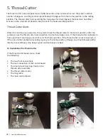
Страница 22: ...e system senses the thread cutter home position the machine beeps once If the thread cutter is already in home position it also beeps once If it can t find home position if the thread cutter is not connected or if there is another problem preventing it going to the home position it beeps one time followed a little later by a second beep One beep is good and two beeps are bad To troubleshoot the th...

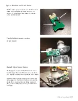
Страница 23: ... Two hall effect sensors on the circuit board Blade Driving Screw Washer Washer s are used under the blade drive screw head to adjust the end of the screw up and down so it engages properly with the thread cutter blade If the screw is too short the end of the screw will not engage into the hole in the blade to move the blade If it is too long the end of the screw will drag on the needle plate bind...

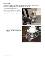
Страница 24: ...ove the two needle plate screws 2 Carefully remove the needle plate and tip it over onto the hook frame taking note of which way you twist the wires so you can untwist them when you replace the needle plate   IMPORTANT Before changing the blade take note of the small screw end that goes into the hole in the cutting blade it will need to be in the new blade after it is replaced and the thread cut...

Страница 25: ...ade 4 Replace the blade and the thread cutter assembly Make sure the small end of the drive screw engages into the hole in the blade as you replace and tighten the screws 5 Check for any excess cable and tuck it into the frame extrusion Make sure to untwist the wires the proper direction when remounting the needle plate Thread Cutter Blade Driving Screw End Blade Orientation ...

Страница 26: ...e extrusion if pulled out during work on the thread cutter or when the needle plate is removed U U CAUTION Care should be taken when the needle plate is removed to not pull the wires out or wrap them so they are closer to the hook Warn users Thread Cutter Connections There are two connections from one wire sheath at the front for the thread cutter and one connector at the back which connects to J2...

Страница 27: ...ool blade and the right magnet NOTE The set screw is positioned between the two magnets on the thread cutter hub Use a hex 050 1 27mm tool to tighten the screw The set screw would be tightened here U U CAUTION The screw that may get caught on the thread cutter hook if the hook is set too close   IMPORTANT Do not position the set screw om the flat The flat on the shaft is not used on the thread c...

Страница 28: ...tool to tighten the set screw To test the thread cutter Plug in the thread cutter and press the thread cutter button on the Main screen If you ve configured a handlebar button to perform a thread cut you can also press that button   IMPORTANT The thread must be pulled tight for the thread cutter hook and cutter to work properly In other words if one pulls away from the needle plate and then move...

Страница 29: ...Materials Thread Cutter QM59105 Item Part Number Description Quantity 1 QM13110 Needle Plate TC DM 1 2 QM13115 Plate Blade Retainer TC DM 1 3 QM13057 Blade Thread Cutter 1 4 QM13233 Screw 2 56X1 8 Phil Flat HD Undercut 4 5 QM23021 Motor Thread Cutter DM 1 6 QM13114 Plate Mount TC DM 1 7 QM10945 Screw M3X 5X8 Phil Pan HD 3 8 QM13236 Screw M2 5X4 Phil Pan HD SS 2 9 QM23061 Board Thread Cutter DM 1 1...

Страница 30: ...n facing the hand wheel at the rear of the machine direction of motion is when the hand wheel is turned counter clockwise 120 o Position 2 Direction of rotation Position 1 NOTE An exception to the rule is the pitman on the Head Frame Short Shaft The pitman screws are 90 from the first screw to the second screw instead of 120 The screw that is only 120 before the next screw is the first screw when ...

Страница 31: ...HQ Infinity Service Manual 31 Rear main shaft timing pulley flat Head frame pulley main shaft flat Pitman Short Shaft Hole for first pitman screw with pinned end Flat for head frame lower timing pulley ...

Страница 32: ...me lower shaft Hook Shaft Hook shaft pulley small tooth motor Hook shaft pulley large tooth timing Hook shaft pulley small tooth motor Hook shaft pulley large tooth timing Hook shaft rear flats Hook shaft front step down for the hook Small Large Small Large ...

Страница 33: ...HQ Infinity Service Manual 33 Take up Lever Take up lever pitman flat Rear Axle Assembly Short axle flat for shaft coupler Long axle flat for shaft coupler ...

Страница 34: ...has two ball bearings in mounts that are pressed onto the shaft at the rear of the machine One is pressed onto the shaft in front of the two pulleys and the other is pressed onto the shaft behind the two pulleys NOTE The front two bearing retainers each have a sintered iron bearing which slides freely on the hook shaft They do not play a part in maintaining axial play in the machine The rear beari...

Страница 35: ...set screws are oriented to the front of the machine The back pulley is the large tooth pulley for the double sided timing belt The flange and set screws are oriented to the back of the machine To check the rear hook shaft Any gap in this assembly is set to be between the two pulleys In other words the front pulley is pushed towards the front spacer and bearing internal race and then tightened The ...

Страница 36: ...y the hand wheel is stepped down on the front edge to ride against the back bearing inner race and will help hold the ball bearings into the rear frame bulkhead This keeps the main shaft from being able to shift forward The main shaft encoder with its flange to the back is next just inside the rear frame bulkhead It has to be placed on the shaft before the rear bulkhead and bearings are pressed on...

Страница 37: ...f the machine and positions the pulley to be in line with the timing belt To check the main shaft 1 Check for axial play in the top long main shaft by pushing and pulling on the hand wheel 2 Check that the small shoulder on the rear main shaft timing pulley by the hand wheel is up against the inner race on the rear ball bearing 3 Check that the top pulley in the front gear box of the head frame is...

Страница 38: ...two bearings are pushed to a flange in the head frame casting The step collar is pushed against the inner race of the front bearing to hold it in place The ball bearing behind the pulley is held in place by an internal snap ring in the head frame The bottom pulley is adjusted to the rear against the inner race of the ball bearing to keep the bearing in place Locktite Shaft Lock is also used to kee...

Страница 39: ...usion 3 Check the wheels for flat spots or damage Adjusting wheel bases To level the machine 1 Check that each wheel mount is fully seated firmly into the lower frame extrusion 2 Check the wheels for flat spots or damage 3 Place the machine on the flattest surface available This may be the carriage on the frame after the frame is levelled or on a very flat table or counter NOTE Most surfaces are n...

Страница 40: ...o the machine with screws that use a 4mm hex tool NOTE You can use the 16mm 5 8 thin frame wrench QM09318 114 to hold the rear long or short shaft axles while tightening or loosenin the rear wheel retaining screw if necessary Differences between the four wheel axle housings Each of the four wheel bases is unique because they each have a unique purpose The front two housings are for regular type wh...

Страница 41: ...d mounting holes are not elongated for adjustment Front right housing has cutout for the HQ Pro Stitcher Y rack no axle no slotted hole between the four mounting screws NOTE All four mounting holes are elongated for adjustment circled at right Rear left housing has no cutout for the HQ Pro Stitcher Y rack short axle slotted hole between the four mounting screws and mounting holes are not elongated...

Страница 42: ...r adjustment Aligning wheels to correct width for carriage tracks If the machine wheels are too close together or too far apart they can be adjusted on the right side of the machine to be the correct width The wheel axle housings on the right side have elongated mounting screw holes for width adjustment To check wheel alignment Make sure the machine wheels align properly to the carriage tracks To ...

Страница 43: ... the carriage tracks 5 Fully tighten the eight mounting screws on both wheel axle housings and the two shaft coupler screws NOTE If the short shaft shifted during this process ensure the encoder disc is still centered in its sensor and not rubbing on it NOTE Ensure the long axle has proper engagement into the shaft coupler If necessary loosen the screws on the short axle and reposition the shaft c...

Страница 44: ...er oppose each other for optimum balance through out the machine s entire speed spectrum to resolve vibration issues To correct reciprocating counterweight timing 1 Raise the needle bar to its highest position top dead center or to where one of the two counterweight set screws is accessible 2 Use a 2 5mm hex tool to loosen the set screw on the counterweight crank NOTE Ensure you loosen the larger ...

Страница 45: ...not bind and that there is no unnecessary noise 8 Check that both set screws are fully tightened 11 Belt Tension Motor to Hook Shaft Drive Belt Tension To check motor to hook shaft drive belt tension The motor belt should be adjusted to have immediate transfer of motion from the motor to the hook shaft without placing any undue pressure onto the motor shaft bearings or make the machine hand wheel ...

Страница 46: ...lt adjustment Hook Shaft to Main Shaft Belt Tension To check hook shaft to main shaft belt tension The long belt from the hook shaft to the main shaft is the timing belt in the machine It has larger more robust teeth than the motor belt This ensures that the belt is very difficult to slip so timing will be maintained at the timing belt The timing belt should be adjusted to have immediate transfer ...

Страница 47: ...3mm open end wrench retighten the 5mm hex screw 3 Rotate the hand wheel to check for immediate transfer of motion and no binding or tightness in the machine 12 Belt Idler Flange Position Position of Timing Belt Idlers Flanges The three timing belt idlers have a single flange The idlers on the first HQ Infinity machines used a different size spacer behind them depending upon whether the idler flang...

Страница 48: ...tion of the idler flange whether it is inside or outside and the size of the spacer washer used whether it is thick thin or the same   IMPORTANT The machine assemblers are at liberty to set the flanges inside or outside as they determine best for each machine to achieve optimal belt tracking NOTE Use a 5mm hex tool for the idler fixing screws 13 Presser Bar Height The hopping foot mount has abou...

Страница 49: ...lamp screw has been tightened or it can prevent the clamp from being properly tightened on the two bars NOTE A few machines were built with a smaller screw that uses a 0 7mm tool Later a larger screw was used that requires a 0 05 1 27mm tool The upper rear bar in its lowest position should ideally be even with not above or below the lower head frame bushing bottom edge The collar on the upper rear...

Страница 50: ... a 2 5mm hex tool into the access hole in the right front mahine cover and loosen the clamp screw 4 Rotate the hopping foot ring to be centered over the needle plate hole pull down on tool blade to insure pressure is placed on felt piece inside the machine and then firmly tighten the presser bar clamp screw 5 Check that the hopping foot ring is no more than 0 5mm above the plate and centered on th...

Страница 51: ...n with the needle plate hole 4 Center the needle in the needle plate hole by moving the hook frame slightly forward or back as necessary 5 Provide resistance against the adjustment by holding the hook frame while tightening the right side screws first until snug 6 Tighten the left screws until snug 7 Fully tighten the right screws then the left screws again 8 Check to make sure the hook frame did ...

Страница 52: ...e making this adjustment ensure that the needle is straight Use a size 16 100 MR needle 1 Use a 2 5mm hex tool to remove the two front covers Use a 10mm wrench to loosen the three bulkhead bolts slightly about one third of a turn 2 Use a 2 5mm hex tool to loosen the two adjusting screws one on each side of the head frame 3 Rotate the hand wheel until the needle eye is about even with the needle pl...

Страница 53: ...with the needle Loop lift is the radial position of the hook to the needle commonly referred to as timing Another part of timing is hook to needle distance or the axial distance from the hook point to the needle scarf Loop lift is the radial setting of the hook and hook to needle distance is the axial setting of the hook Both of these adjustments are set on the hook and fixed with the same screws ...

Страница 54: ...g This will help you know what needs to be corrected before beginning the timing adjustments This section of the manual reviews how to check timing before you adjust timing Passing Window Stop Finger Opening Hook Point Gib Race Opening Thread Lifting Cam Needle guard Notch Set Screw Flat Set Screw Race Opening Thread Cutters ...

Страница 55: ...e bar must have a plastic protective piece on the clamp screw to prevent damage to the needle bar wear surface 2mm ball end L hex tool QM40215 2mm hex tool QM40216 with handle 2 5mm hex tool QM40217 with handle 3 flat screwdriver QM40218 A new straight needle system 134MR size 16 100 crank needle NOTE Roll the needle on a flat surface like the needle plate while watching the point for wobbles a st...

Страница 56: ...e taking note of which way you twist the wires so you can untwist them when you replace the needle plate   IMPORTANT Do not twist or pull out the wires so they will get caught in the rotating hook when the needle plate is reinstalled The wires must be tight up into the wire channel in the casting and away from the hook as much as possible to have minimal exposure to the hook 3 Use a 1 Phillips s...

Страница 57: ... clamp and the bottom of the head frame needle bar bearing surface with the machined edge facing up 8 Raise the clamp on the needle bar up against the feeler gauge reset and tighten the clamp pinching the 2 6mm feeler gauge in between the clamp and the bearing surface At this point the needle bar is still BDC This step may need to be repeated a few times in order to remove all excess play between ...

Страница 58: ...on mistakes made by newer technicians is turning the hand wheel the wrong direction clockwise during this step or when making the actual adjustment NOTE Another common mistake is the technician does not turn the hand wheel at all and therefore sets the hook to the needle at BDC instead of at 2 6mm loop lift NOTE If the hand wheel is turned too hard the clamp will slip on the needle bar making the ...

Страница 59: ...This is a very precise setting and is set to rub only about 001 inch one thousandth of an inch or less 13 Check needle bar height When the hook point reaches the far side of the needle the bottom of the hook point is 1mm above the top of the needle eye NOTE In 99 of cases needle bar height does not slip If it is off it was changed or improperly set by a technician The first thing an inexperienced ...

Страница 60: ...sket needle guard may deflect the needle making it difficult to accurately adjust the needle distance between the hook and the needle scarf One can be deceived into thinking that there is no gap between the hook and needle scarf and that the needle distance is correct In actuality the needle is far too close and is rubbing far too hard on the needle guard thus causing unnecessary hook noise and we...

Страница 61: ... moved away from the basket You are now ready to adjust loop lift and needle distance timing   IMPORTANT If needle bar height has been changed or is not set close to correct or correctly it will not be possible to set needle distance because the hook will not pass through the scarf to set the needle distance For more information about needle bar height see Needle Bar Height timing Loop lift and ...

Страница 62: ... the hook to needle distance First push the hook on or off the hook shaft as needed until the hook lightly touches or brushes the needle inside the needle scarf Then roll the hook point to the far side of the needle to set the loop lift This is most easily done if one provides some resistance against the adjustment 5 While holding onto the hook to provide some resistance against the adjustment tig...

Страница 63: ...vily The needle distance in this case should be increased until the hook is lightly touching or rubbing in the needle scarf 10 Carefully tighten both hook screws very tight to hold the timing setting 11 Check the setting one more time with the clamp and gauge to ensure nothing changed while tightening the hook 12 Replace the stop finger See To check the stop finger in section 15 Timing 13 Turn the...

Страница 64: ... Additionally HQ Infinity uses the 134 MR needle system crank needle which helps to prevent the needle from being deflected too far away from the hook as fabric pushes the needle especially at the high stitching speeds up to 3100 SPM Stop Finger The stop finger holds the bobbin case basket from turning and provides an escapement gap for the top needle thread to complete its loop around the bobbin ...

Страница 65: ...top finger The engagement of the stop finger and throat of the bobbin case support basket must have a clearance of 8mm to 1 0mm NOTE This clearance ensures that there is adequate space for thread escapement during the sewing process 8mm to 1 0mm ...

Страница 66: ...nstalled and the loop lift adjustment is made with a visual check For example during assembly use a cylinder height gauge to set needle bar height first However after the hook is installed and timed you can check needle bar height to avoid having to remove the hook to check needle bar height and then have to retime the machine NOTE Needle bar height has to be set correctly enough before the timing...

Страница 67: ... groove oriented straight out to the front and the needle pushed all the way up to the stop sight hole in the needle bar clamp NOTE Make this adjustment after the loop lift has been first set correctly NOTE The needle bar height rarely will slip or change If it is off it was changed or improperly set by a technician Before you change needle bar height make sure that the adjustment is necessary and...

Страница 68: ...and so the needle bar will not fall out of the driver U U CAUTION Under no circumstances should the needle bar clamp set screw be completely loosened If it is completely loosened the needle bar can uncouple from the needle bar driver If this happens do not run the machine Remove the front right cover reassemble the needle bar to the needle bar driver and readjust 6 Loosen the needle bar driver cla...

Страница 69: ...osition the eye of the needle should be aligned with the white line on the gauge The bottom of the eye should align with the bottom of the white line A little of the gauge black can barely show at the bottom of the eye To adjust needle bar height using the cylinder height gauge with hook out of the machine   IMPORTANT Before making this adjustment ensure that the needle is straight Use a size 16...

Страница 70: ... the hook shaft and roll the flat down 4 Lower the needle bar to the lowest position 5 With the flat down on the cylinder tool slide the cylinder tool gently against the needle 6 Place a 3 flat screwdriver blade through the access hole in the right front cover and head frame Eye aligned with white groove ...

Страница 71: ...the eye should align with the bottom of the white line A little of the gauge black can barely show at the bottom of the eye 9 Ensure the needle bar thread guide hole is straight towards the front of the machine where the user stands to use the front handle bar If necessary rotate the needle bar radially until it is straight towards the front 10 Fully tighten the clamping screw in the needle driver...

Страница 72: ... have a 4A fuse which may be replaced with a 5A fuse when necessary If you suspect the fuse has blown first check the following Make sure the power cord is plugged into the power entry module at the rear of the HQ Infinity and the power switch is in the On position Press the front power switch making sure it is in the recessed On position Check for power to the outlet you are using by plugging in ...

Страница 73: ...wo very small flat head screwdrivers or two old needles pulling outward at the same time you are pressing them in toward each other 2 Pull the box out and examine the fuse It may be necessary to use an ohm meter or continuity tester to verify whether the fuse is still intact Replace the fuse if it is blown no continuity from one end to the other usually the glass is blackened as well ...

Страница 74: ...timately be connected to both the machine chassis and the Earth Ground wire of the power cord for safety One of the earth ground wires green yellow should be connected to the power outlet side from the center ground pin of the outlet to one of the outlet mounting screws Another earth ground wire connects the power inlet from one of the inlet mounting screws to the earth ground screw terminal on th...

Страница 75: ...are pressed completely onto the tabs The AC wires between the inlet and outlet have right angle connectors intended to connect to the tabs on the outlet   IMPORTANT When connecting the AC wires remember blue neutral brown line or primary Although the blue wire is labeled neutral it may actually be powered depending upon how the power source is wired The power outlet and inlet as well as the 48VD...

Страница 76: ...76 www HandiQuilter com 18 Handlebar Switches The arrows below indicate cable connections Membrane switches are attached to their cables ...

Страница 77: ...dlebar switches LED control signals Thread tensioner controls Thread break sensor signals Needle laser control Front power switch control The cable from the power supply side contains the 48V necessary to power the front distribution board and LED lighting Remove the plastic trough cover gently prying upward on the plastic insert with a large screwdriver Be careful not to mar the paint or damage t...

Страница 78: ...rear handlebars casting to the back of the HQ Infinity 4 Use a 4mm ball hex tool to remove the four screws that attach the rear handlebars casting to the back of the HQ Infinity NOTE Photo shows display removed 5 Carefully set the rear handlebars casting aside To install the rear handlebars Follow the disassembly instructions in reverse   IMPORTANT When connecting the USB and power cables be sur...

Страница 79: ...stic panel for access to the control board and the DC brushless motor Rear panel screws All screws are M4 of different lengths with washers Far back position 3 X M4 x 20mm Back side positions 4 X M4 x 16mm To remove the right rear panel 1 Remove the rear handlebars as described on the previous page Right rear plastic panel Left rear plastic panel ...

Страница 80: ...move the two screws on the left side of the rear connector plate leaving the two screws on the right side 3 Use a 2 5mm hex tool to remove the seven screws shown four on the right panel and three on the left panel 4 Carefully remove the right side plastic panel ...

Страница 81: ...e machine leaving the two screws on the left side 3 Use a 2 5mm hex tool to remove the seven screws shown on the left rear panel To install the rear plastic panels 1 Check the rear connector plate for any loose cables 2 Check the quick connect terminals on the outlet and inlet to ensure that they are fully seated 3 Check that the main 20 pin cable assembly is fully engaged in the receptacle on the...

Страница 82: ...llowing the disassembly instructions above in reverse 5 If both panels have been removed first attach two of the rear connector plate screws to one of the side panels and attach that panel first 6 Then attach the other panel Be aware that there is a plastic section on the right side panel that keeps the rear cables away from the belts As you attach the panels make sure this divider does not pull a...

Страница 83: ...n damping hardware Remove the left front panel to access the front main circuit board thread tension motor and thread break sensor Due to how the left and right front panels interlock both sides should always be removed simultaneously U U CAUTION Removing only the front left or right panel while the opposite side is still mounted to the machine may damage the panels Left front plastic panel Right ...

Страница 84: ... 12 with M4 washer M4 x 12 with M4 washer Left front cover screws when facing cover A Top left 18mm 20mm B Center left 12mm 12mm C Bottom left 16mm 20mm D Top right 20mm 20mm E Center right front 16mm 20mm F Bottom right 12mm 12mm U U CAUTION Never use a longer screw in place of a 12mm screw in the shallow hole at center left position B because it will interfere with and damage the timing belt in ...

Страница 85: ...e a 2 5mm hex tool to remove one screw on the front right panel and six on the left front panel 3 Remove the panels by first carefully separating the two panels toward the front of the machine and then pulling forward gently on the two panels to pull them out from under the flange of the bulkhead The two panels should then easily pull apart from each other to be removed from the machine ...

Страница 86: ...ith the corresponding parts on the head frame 2 Align the slit in the panel with the screen bracket and angle the right panel slightly to fit the rear portion of the panel under the flange of the bulkhead and then gently press the panel in place against the head frame 3 Use a 2 5mm hex tool to attach the right panel to the head frame with a 12mm screw and washer ...

Страница 87: ...me See the chart above and refer to the photo to properly place each of the screws 23 48V Power Supply QM23003 A failed power supply will not allow power to be delivered to any of the rest of the Infinity Therefore you will not have any LEDs on any boards including the green LED at the top of the 48V power supply Since identifying a failed power supply can be difficult before replacing the power s...

Страница 88: ...ls NOTE If this cable is unplugged or damaged you will be unable to turn off the machine with the front switch The machine will turn on when the rear switch is in the On position regardless of the state of the front switch To remove the power supply 1 Remove the right rear plastic panel See To remove the right rear panel in section 21 Rear Plastic Panels 2 Use a 3mm hex tool to remove the four scr...

Страница 89: ...s of the power supply 6 Carefully pull the remote power switch cable from the connector near the green LED Pull on the plastic housing and not on the wires To install the power supply 1 Use a Phillips screwdriver to connect the brown blue and two green yellow AC wires to the bottom terminals of the power supply Green yellow goes closest to the outside edge blue in the middle and brown closest to t...

Страница 90: ...longated mounting holes to allow for side to side adjustment With the four mounting bolts loose shift the power supply as far toward the front of the machine as possible and tighten the bolts with a 3mm hex tool 8 Reinstall the plastic panels 24 Front Distribution Board QM23005 U U CAUTION Electronic components can be damaged by electrostatic discharge ESD Follow all ESD precautions in the Electro...

Страница 91: ... the connector out of the housing Connectors with only two or three wires should never be pulled loose by the wires U U CAUTION Be especially careful removing the 2 pin laser connector It is a very tight connector and the wires can be easily damaged It may be easiest to use a pair of pliers to pull the connector out of the housing   IMPORTANT The left and right handlebar cable connectors are ide...

Страница 92: ...rewdriver to attach the board to the head frame with the four mounting screws 3 Attach the cables as shown Be sure the cable leading to the right handle switches plugs into the top of the two 8 pin connectors and the cable to the left handlebar plugs into the bottom 4 Reattach the front plastic panels See To install the front plastic panels in section 22 Front Plastic Panels U U CAUTION Take care ...

Страница 93: ...e Rear Plastic Panels section of this manual 3 Disconnect all cables plugged into the front distribution board Be extremely careful to not damage any of the wires   IMPORTANT Always try to pull on the plastic connector rather than pull on the wires directly The large connectors with multiple wires can be pulled by the wires if you make sure you pinch the middle portion of those cables so you are...

Страница 94: ...f the board have identical connectors If they are not already labeled label these cables with tape before removing them to ensure they are reinstalled in their proper locations Label the connectors J2 J3 J5 J6 and J7 Â Â IMPORTANT It is possible that two of the USB connectors are not keyed If this is the case make sure the red wire of those cables is on the left 6 Use a 1 Phillips screwdriver to r...

Страница 95: ...rs and large capacitors should be at the bottom 3 Use the three longer clamp screws and the clamping bar to clamp the drive transistors to the thermal pad Snug these screws firmly being careful not to over tighten If the clamping bar begins bending the screws are too tight 4 Firmly tighten the main control board screws 5 Attach the cables as shown 6 Attach the rear right panel See To install the r...

Страница 96: ...flash periodically in an idle state or regularly during display use The icon in the top left hand corner of the front display screen is red The front display is not responding On startup the values in Manual speed or Regulated SPI are zero on the front display Corrective Measures Be sure the display USB cable is plugged into the front left upper USB connector Check the USB connections on the upper...

Страница 97: ...her is connected and is powered up Motor Error icon at the top right corner of the Pro Stitcher screen Corrective Measures Make sure the Pro Stitcher data cable is plugged into the rear of the Infinity and the rear of the Pro Stitcher carriage and that the power cable is connecting the rear panel to the carriage NOTE If the front RS232 connection is not functioning see previous section the Pro Sti...

Страница 98: ...gulated SPI are zero on the rear display Corrective Measures Be sure the rear USB cable is connected between the rear display and the top USB connection on the rear panel Make sure the internal USB cable from the rear panel is connected to the J6 USB connector on the main control board 4 Rear Display RS232 Connection Communication between the USB hub and the processor runs through a USB to Serial ...

Страница 99: ...ration When the Infinity boots up this LED should be on Faulty Operation Symptoms The LED will be off if the hub is not functioning properly The USB camera will not function when plugged into either the front bottom camera USB port or the rear lower USB port Corrective Measures Make sure the front display is properly plugged in to both the power and USB ports on the front board Verify the internal...

Страница 100: ... in the normal direction of motion counterclockwise when looking from the rear of the machine the LED should toggle ON just as the take up lever reaches its highest point in the stitch cycle This is the Needle Up position The needle at this point is on its way down but should still be slightly above the hopping foot Faulty Operation Symptoms The LED does not toggle either on or off over a full rot...

Страница 101: ...haft encoder disc in the Main Shaft Encoder section of this manual Check for damage to the main shaft encoder the black forked sensor shown above that may have been caused due to misalignment of the encoder disc causing the disk to collide with the sensor Replace the sensor and or adjust the disc as needed See the Main Shaft Encoder Sensor section of this manual 7 Thread Break Sensor LED TEST 2 No...

Страница 102: ...ion of this manual If adjustment of the sensor does not resolve the problem it may be necessary to replace the sensor See To replace the thread break sensor in the Thread Break Sensor section of this manual 8 Heartbeat LED This LED is an indicator that the main processor on the control board is functioning properly Normal Operation The LED flashes in a heartbeat fashion when the control board has ...

Страница 103: ...l all the LEDs go off before disconnecting any cables Inspect the cable and device connected to that cable and repair or replace it as needed 9 TEST 3 LED This LED is currently not used 10 3 3 Volt Supply LED 11 5 Volt Control Board Supply LED 12 5 Volt Motor Driver Supply LED LEDs 10 11 and 12 indicate various voltage levels that are being generated on the main control board If any of these LEDs ...

Страница 104: ... damaged by Electrostatic Discharge ESD Follow all ESD precautions in the Electrostatic Discharge ESD section at the front of the manual while handling the arm LED board To remove Arm LED board 1 Use a 1 Phillips screwdriver to remove the two arm LED mounting screws 2 Carefully detach the cable from the arm LED board making sure to pull on the plastic connector and not the wires To install the arm...

Страница 105: ...r to mark one side of the cable and the back of the board closest to that side of the cable to ensure you can correctly reinstall the cable later Then unplug the switch cable from the back of the board To install the left or right handle LED board 1 Plug the handlebar switch cable into the back of the LED board matching the marking placed on the cable during removal with the marking on the board N...

Страница 106: ... cable into the connector on the hook LED board 2 Use a 1 Phillips screwdriver to mount the hook LED board with the connector facing the rear of the machine as shown in the previous image Hook LED Cable QM23017 U U CAUTION Electronic components can be damaged by Electrostatic Discharge ESD Follow all ESD precautions in the Electrostatic Discharge ESD section at the front of the manual while handli...

Страница 107: ...he cable trough so the connector doesn t get caught To install the hook LED cable NOTE If you have used a guide wire or string simply pull the cable through using the guide wire Make sure the cable stays in the trough in the lower arm Otherwise follow the steps below 1 Thread one end of the hook LED cable through the right side trough under the Infinity just behind the hook 2 Push it back toward t...

Страница 108: ...ht panel See To install the rear plastic panels in section 21 Rear Plastic Panels LED Ring QM23025 U U CAUTION Electronic components can be damaged by Electrostatic Discharge ESD Follow all ESD precautions in the Electrostatic Discharge ESD section at the front of the manual while handling the LED Ring To remove the LED ring 1 Remove the front plastic panels See To remove the front plastic panels ...

Страница 109: ...3 Mount the LED ring to the head frame with two Phillips screws using a short 1 Phillips screwdriver 27 Thread Tension Sensor and Motor Thread Tension Sensor Board QM23067 U U CAUTION Electronic components can be damaged by Electrostatic Discharge ESD Follow all ESD precautions in the Electrostatic Discharge ESD section at the front of the manual while handling the Thread Tension Sensor Board To r...

Страница 110: ...from the board To install the thread tension sensor board NOTE It may be easier to install the thread tension sensor board if the thread tension motor is out of the way See To remove the thread tension motor in section 27 Thread Tension Sensor and Motor 1 Check the black sensor protruding from the back of the sensor board and straighten if necessary so it is perpendicular to the sensor board ...

Страница 111: ...ION Electronic components can be damaged by Electrostatic Discharge ESD Follow all ESD precautions iin the Electrostatic Discharge ESD section at the front of the manual while handling the Thread Tension Motor To remove the thread tension motor 1 Remove the front plastic panels See To remove the front plastic panels in section 22 Front Plastic Panels 2 Remove the thread tension sensor board QM2306...

Страница 112: ...o M3 screws 2 Reinstall the front panels See To install the front plastic panels in the Front Plastic Panels section of this manual Thread Break Sensor QM23087 U U CAUTION Electronic components can be damaged by Electrostatic Discharge ESD Follow all ESD precautions in the Electrostatic Discharge ESD section at the front of the manual while handling the Thread Break Sensor To adjust the thread bre...

Страница 113: ...actuate the check spring and verify that the sensor is as close as possible to the spring without rubbing on the spring 6 Tighten the set screw with a 2mm Hex tool just until snug Over tightening the set screw may damage the sensor NOTE The set screw for the thread break sensor has a plastic tip to minimize damage to the sensor Replace only with an identical set screw if necessary QM10890 7 Press ...

Страница 114: ...s attached 4 Pull the sensor out from the left hand side of the head frame by gently pulling on the sensor cable If necessary use a small blunt tool such as a 2mm or 2 5mm hex tool to gently push the green end of the sensor on the right side of the head frame while pulling on the gray cable on the left side of the head frame and remove the sensor from the head frame 5 Because the sensor cable is r...

Страница 115: ...he front of the manual while handling the Needle Laser To adjust the needle laser 1 Remove the front plastic panels See To remove the front plastic panels in section 22 Front Plastic Panels 2 Turn on the Infinity but take care to not short anything out on the front distribution board while it is on Make sure you do not accidentally start the machine 3 Insert a large flat screwdriver downward betwe...

Страница 116: ...ove the front plastic panels See To remove the front plastic panels in section 22 Front Plastic Panels 2 Disconnect the 2 pin laser connector from the front distribution board Be especially careful as it is a very tight connector and the wires can be easily damaged With this connector it may be easiest to use a pair of pliers to pull the connector out of the housing 3 Remove the two cable clamps s...

Страница 117: ... the wires as they are very fragile 5 Carefully remove the laser and laser post together from the head frame do not attempt to remove the laser from the post To install and position the needle laser The laser and mounting post come preassembled 1 Place the laser post in place at the front of the head frame with the wires up and the laser lens down pointed toward the needle ...

Страница 118: ...the screws loose so you can still adjust the laser post 3 Plug the laser cable into the 2 pin connector on the front distribution board 4 Route the laser cable with the other cables and use a 1 Phillips screwdriver to mount the two cable clip s back in position Take care not to pinch or damage any cables with the clips or the screws ...

Страница 119: ...Tape the fabric or paper in place to keep it stationary while cycling the needle to pierce the paper or fabric 7 Raise the needle and then use a 2 5mm hex tool to adjust the laser to aim at the piercing 8 Tighten the two Phillips screws to hold the laser in position 9 If the laser moves while tightening the screws either loosen the screws and try again or follow the previous instructions for adjus...

Страница 120: ...Main Shaft Encoder Sensor is unplugged or malfunctioning one of two things will happen 1 The needle will cycle continuously at a slow speed when the Needle Up Down button is pressed 2 The needle will cycle briefly and then an error message will appear regarding a Main Shaft Encoder Fault For each of the above situations check that the main shaft encoder cable is plugged into the main control board...

Страница 121: ...e the right rear panel in section 21 Rear Plastic Panels 2 Power up the quilting machine but do not to start the motor i e do not quilt 3 Use a 2mm hex tool loosen the set screws in the main shaft encoder disc 4 Rotate the hand wheel counterclockwise looking at it from the rear until the take up lever is in the highest position The needle should be on its way back down but the tip of the needle sh...

Страница 122: ...machine power wait for the LEDs to all go off and turn it back on again This forces the processor to re set the Needle Up Down positions that have been stored in memory 9 Temporarily put on the left rear panel using one 16mm screw This will help to keep the cables from rubbing on the belt 10 Test the stopping position of the needle by pressing the Needle Up Down button on either handlebar When the...

Страница 123: ...that mount the main shaft encoder disc to the main shaft Rotate the hand wheel as necessary 3 Rotate the main shaft encoder disc so the open section of the disc is oriented downward and push the disc along the shaft toward the front of the machine to get it out of the way of the encoder sensor Be careful not to push it too far or it will be difficult to pull it back into position later 4 Use a 5mm...

Страница 124: ...d to the machine 6 Remove the top channel plastic insert by gently prying upward being careful not to damage any of the cables in the channel 7 Remove the two main shaft center bearing block mounting bolts with a 5mm hex tool 8 Unplug the main shaft encoder sensor cable from the control board at J42 ...

Страница 125: ...w sensor cable back through easily 10 With the rear bulkhead and center bearing block loose gently push the main shaft to one side or the other to gain access to the main shaft encoder mounting bolts It may be necessary to tap lightly on the side of the bulkhead with a rubber mallet if it is really tight 11 Use a 2 5mm hex tool to loosen the two sensor mounting bolts Push ...

Страница 126: ...wire from the cable making sure you can use the string or wire to attach to the replacement sensor and pull it back through The string or wire will also help keep the sensor standoff in position for the replacement sensor To install the main shaft encoder sensor Installation of the main shaft encoder sensor is based on the rear bulkhead and center bearing block being loose as explained in the Remo...

Страница 127: ...goes down through the plastic standoff piece and then down through the hole in the bottom of the upper extrusion 4 Gently push the main shaft to one side or the other as you guide the new sensor down in position on top of the encoder standoff The two screws should go through the outer holes in the plastic standoff and down into the upper extrusion You should be pulling the end of the guide wire at...

Страница 128: ...he guide wire string from the sensor cable and plug the sensor cable into the J42 connector on the main control board 7 Align the rear bulkhead bolts and use a 5mm hex tool to loosely install the six bulkhead bolts to mount the rear bulkhead to the machine After all six are loosely installed tighten each one in an alternating pattern 8 Install the two idler pulleys with spacers as shown using the ...

Страница 129: ...T Remove the needle just to be safe 11 Using the rear hand wheel rotate the main shaft until the take up lever is in its highest position this is the Needle Up position 12 Slide the main shaft encoder disc back in position between the sensor forks the cut out portion facing down to get the disc over the first prong of the sensor fork 13 Follow the instructions in the Main Shaft Encoder Disc Adjust...

Страница 130: ...is moved left and right across the frame The Y direction encoder is mounted to an axle between the rear machine wheels of the Infinity If the Y Encoder is not functioning properly the stitches in the Y direction front back will usually be elongated The quilter may notice that when quilting strictly front to back or back to front they could have no stitching at all If this occurs check the followin...

Страница 131: ...he Y encoder that will likely pull loose as you do this If it does not detach on its own reach in behind the encoder and disconnect the cable 4 Loosen the two set screws in the spiral coupler closest to the Y encoder with a 2mm hex tool 5 Pull the encoder and wheel hub end of the axle assembly out of the spiral coupler 6 Use a 1 Phillips screwdriver to remove the two Phillips screws that hold the ...

Страница 132: ...ut is not likely to be necessary Remove the two Phillips screws shown to remove the rear housing To assemble the Y encoder 1 Replace the rear housing piece if it was removed using the two Phillips screws shown in the last step of the removal process 2 Place the optical disc on the shaft with the bulk of the collar facing away from the encoder assembly Hold together while tightening the disc collar...

Страница 133: ... Attach the front encoder housing with the Phillips screws that were previously removed 6 Slide the encoder half of the rear axle assembly onto the other half of the axle making sure one of the set screws is aligned with the flat on the axle U U CAUTION Do not tighten the set screws on the spiral collar at this point NOTE It will likely be necessary to remove the left rear plastic panel as explain...

Страница 134: ... to determine that position slide the hub in toward the center of the machine and tighten at that position NOTE The two spiral set screws closest to the encoder should still be loose to enable the shaft to slide in or out as needed 11 Press the wheel closest to the Y encoder tight against the wheel hub as shown This will press the shaft into the collar 12 Tighten the collar set screws with a 2mm h...

Страница 135: ... the two motor wire connectors and the motor encoder cable connector from the main control board Try to pull on the plastic connector rather than the wires to avoid damaging the wires 3 Use a 4mm hex tool to remove the four motor plate bolts 4 Carefully slide the motor out of the timing belt and out of the machine casting 5 If the motor mounting plate must be removed use a 3mm Allen wrench to remo...

Страница 136: ...r the machine back on and check to see if the 48B LED comes on If so power off and plug one cable back in at a time until you find the cable leading to the LED board that is causing the short Repair or replace that board and or cable If the LED remains off or very dim after removing all cables the QM23005 board has likely failed and should be replaced No Power to Machine Corrective Measure s One o...

Страница 137: ...quires two sets of DC wires For more information see Section 25 Main Control Board Motor not running Pressing Start or Needle Up Down on the handles results in the system freezing up and the motor not running Corrective Measure s Loose or damaged motor wiring Check to make sure the cables from the drive motor two sets of wires directly from the motor and one from the encoder on the back end of the...

Страница 138: ...ighten the metal clamping bar over the transistors as this could also cause the same failure Tighten those screws firmly but not so tight that the insulator is overly compressed or damaged For more information see Section 25 Main Control Board Motor has failed least likely Replace the motor according to the instructions in Section 30 Drive Motor Front display will not completely boot It freezes be...

Страница 139: ...n on Corrective Measure s No AC power Check the wall outlet with a volt meter and make sure power is available Try another outlet if possible Bad AC Power cord Test with another power cord if available and replace if necessary Blown Fuse Refer to Section 16 Power for more information about replacing the fuse Front switch malfunctioning Test by removing the front switch cable from the top of the po...

Страница 140: ...coupler for rear axle and adjust to proper width Retighten Communication error red icon at top left of display Corrective Measure s USB cable unplugged or in wrong USB port The rear display USB cable should be plugged into the top USB port The front plugs into the back facing USB port Power off and reboot if necessary Noise from reciprocating counter weight piston Corrective Measure s Worn or dry ...

Отзывы: