Chapter 2 - Features set
User Manual
R5000 series - Web GUI
23
Each side of the link (local and remote) has two similar test indicator sets,
corresponding to each antenna polarization (one for Vertical polarization and
another for Horizontal). This allows controlling the alignment process for each
antenna polarization for the local and for the remote device simultaneously.
The text indicators are:
RSSI - indicates the power level of the received radio signal (measured in dBm)
Chain 0 Signal Level - input signal level (measured in dB) indicator of antenna
number 0 (vertical polarization)
Chain 1 Signal Level - input signal level (measured in dB) indicator of antenna
number 1 (horizontal polarization)
Error Vector Magnitude (EVM) - indicator of the measured input signal quality
(it should be as high as possible in absolute value; the recommended level is
not less than 21 dB; some old firmware had EVM value positive, but most the
firmware has negative value, so for the troubleshooting, evaluate the absolute
EVM value)
Retries - percentage of transmit packet retries
Tx bitrate - displays the current bitrate for the remote and local unit (measured
in Kbps)
Graphical indicator:
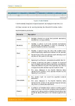
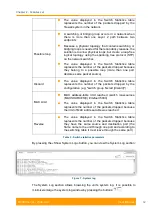
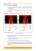
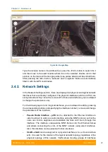
Figure 19 - Alignment test - graphical indicator
The main indicator is the Input Signal stripe.
Содержание R5000 series
Страница 1: ...R5000 series Web GUI Software Version MINTv1 90 11 Last updated 8 31 2014 User Manual ...
Страница 10: ...Getting started Chapter 1 ...
Страница 13: ...Features set Chapter 2 ...
Страница 99: ...Configuration scenarios Chapter 3 ...


