


4
Installation
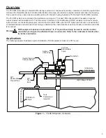
Before starting installation, conduct a site survey to identify potential containment groups. Based on that survey, plan out
which STP sump the equipment will be installed in and how containment areas will be grouped together.
Warning
Lockout and tag circuit breakers, and disconnect console power wiring before installing or servicing
any system wiring.
Warning
DO NOT make solenoid and/or sensor wiring connections with live power connected to the console
or any module.
Warning
TS-SCCM contains aluminum, care must be taken to avoid ignition due to impact.
Caution
Do not run intrinsically safe (IS) wiring and non-intrinsically safe (non-IS) wiring in the same
conduit.
Note:
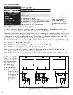
TS-SCCM must be installed in accordance with the national electrical code, ANSI/NFPA 70, CEC or other
applicable national or local codes.
Note:
Maximum torque on supplied hose clamps is 20 inch-lbs.
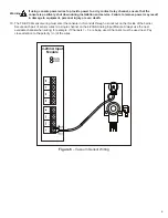
1. Pull all wiring through the conduits that will be used for the TS-SCCM vacuum sensor and solenoid valve. The
intrinsically safe (IS) sensor wiring must be run in an IS conduit. The non-IS solenoid wiring must be run in an
approved explosion proof rigid metal conduit.
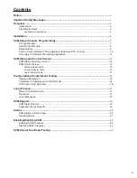
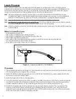
2. Mount the TS-SCCM inside of the turbine
containment area, supported by rigid,
explosion proof conduit. Then orientate the
units to allow enough clearance to make the
vacuum line connections without stretching,
kinking, or creating sharp bends in vacuum
hoses. The SCCM cover is installed with the
label upwards. See Figure 3.
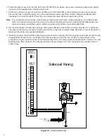
3. Connect the solenoid wiring to the field wiring
using wire nuts to secure the connections.
Replace the explosion proof junction box cover.
4. Connect the vacuum sensor wiring to the IS
field wiring using epoxy wire seals to secure
the connections. Replace the IS junction box
cover.
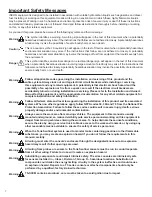
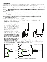
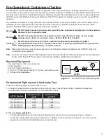
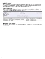
5. Install the supplied Siphon Check Valve with
the inscribed Flow Arrow pointing to the STP.
Apply a non-hardening, thread sealing
TS-SCCM/1
TS-SCCM/2
Figure 3
– Cover Installation (rear view)
compound to the threads, then thread the valve body into the submersible turbine’s siphon port. If necessary, use a
FFS Secondary Syphon Assembly to connect the SCCM to the syphon port of the STP.
Single Syphon (typical)
Secondary Syphon
Assembly
STP
STP
Secondary Syphon Kit
Figure 4
– Secondary Syphon Assembly Installation
Содержание TS-5000
Страница 27: ......
Страница 28: ... 2013 FFS 000 0528 Rev E ...


