


20
Alarms
When a T5 FMS console is in alarm, the Alarm LED on the front of the console will flash. If SCM has been programmed
to shut down the pump on alarm (in the SCM Setup), the pump will be unavailable for all system tests and dispensing
until the containment with the active alarm is manually Reset. If the condition still exists after reset, the alarm will return. A
service visit may be required to identify and correct the condition.
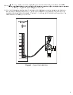
Warning
Always REMOVE POWER from the console prior to installing/removing a module or performing any
maintenance while the console door is open.
Note:
Refer to the Important Safety Messages outlined in the beginning of this manual before performing any console
maintenance.
Note:
If at any time while troubleshooting a Warning or Alarm this guide is not able to help you correct the issue, please
contact FFS Technical Services.
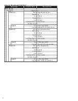
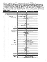
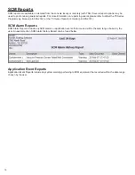
SCM Alarms and Warnings
To troubleshoot your alarm or warning, identify the Alarm/Warning display on the console in the table below and review the
solution presented in the Error Code Table that follows.
Alarm/Warning
Possible Error Codes
Channel Not Learned
G
Failed to Hold Vacuum
A, B, H
Failed to Reach Target Vacuum
A, B, C, D, F
Low Vacuum
A, B, C, D, F
Low Vacuum and Pump Request Ignored
A, B, F, G
Not Configured
G
Not Learned
G
Program Error Detected
Check SCM Programming
Pump Request Ignored
F
Unstable Vacuum
B, D, C
Vacuum Sensor Failure
E
Vacuum Sensor Failure / Not Connected
E
Vacuum Too High
B, G
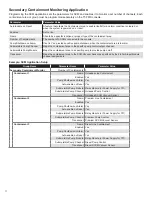
Error Code Error
Solution
A
Containment Tightness
Refer to the Containment Tightness Testing section of this guide and perform the tests in
that section to ensure that there are no leaks and that the tank is tight.
B
Thermal Contraction
Caused by temperature variations of the air (or liquid if present) in the containment.
C
Liquid in Containment
This will decrease the containment size. If liquid is drawn through the containment, through
the STP siphon, various parameters and containment vacuum readings will be incorrect.
Containments should remain free of liquid at all times.
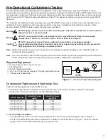
D
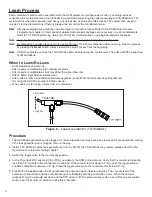
Siphon Function Check The siphon must be able to pull a vacuum of 8" Hg or more if connected to other equipment.
The vacuum also must have a minimum flow rate of 146 L/Hr. Perform a STP Siphon Flow
Rate Test as illustrated in the Pre-Operational Containment Testing chapter.
E
SCCM Vacuum Sensor
Function Check
The transducer is sending incorrect data or no data to the console. Verify wiring from the
transducer to the console. If wiring is correct, setup and program the transducer on a
different, unused channel for testing.
F
STP Function Check
Use the dispenser to signal the STP when the dispenser is authorized then the STP should
run. Also, SCM must be able to signal the STP pump on. Force a test on the containment
using the SCM Control screen. The STP will start only if necessary to evacuate the
containment. If the STP does not run to evacuate the containment, verify programming.
G
Verify Programming
Refer to the SCM Setup chapter of this guide for all SCM related programming information.
H
SCCM Vacuum Relief
Valve Function Check
The mechanical vacuum relief valve is designed to open when containment vacuum levels
reach or exceed 10" Hg. If at any time the containment vacuum level exceeds 10" Hg while
the pump is on, this error will occur as an indication of a relief valve failure.
Содержание TS-5000
Страница 27: ......
Страница 28: ... 2013 FFS 000 0528 Rev E ...


