Interface Card Installation
37
Step 5
Move the front panel of the interface card into the expansion slot opening of the
SmartNode until it fits correctly.
Step 6
Press the interface card gently down until you feel its connector mate securely with the
socket on the motherboard. Take great care to ensure that the card fits correctly in the
connector and is pressed fully home.
Step 7
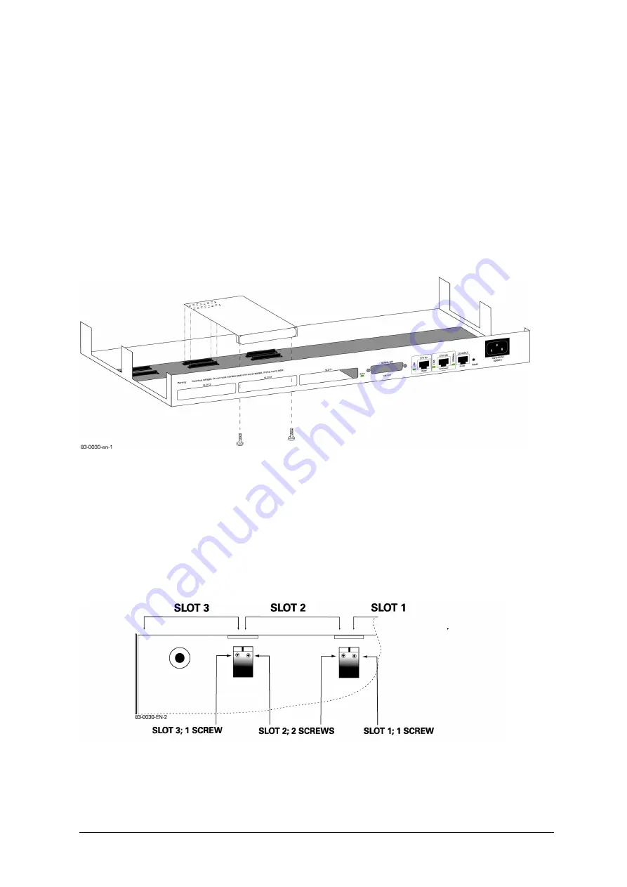
Fix the interface card by replacing the 2 screws into the holes on the bottom of the
SmartNode, using the Phillips screwdriver: See Figure 1 and ’Card Locating Screws’ on
the next page.
Step 8
Replace the cover and secure it to the side panels of the SmartNode chassis by the 9
screws that you removed in Step 3.
Step 9
Reinstall the cables, connect the installed interface card.
Figure 8-1: Example Card Installation in SLOT 2
8.3
Card Locating Screws
Figure 8-2 shows part of the under side of the SN2300 with the arrangement of securing screws for
two of the three interface cards. The two outer expansion slots (SLOT 1, SLOT 3) have each a single
securing screw towards the inner sides. SLOT 2 has two securing screws. (SLOT 1 is similar to SLOT
3 and so is not shown). You can see the location of an extension card’s screw holes in the metal
blocks on either side of the group of four sockets in the jumper pin setting diagrams, which depict
the underside of the IC-4BRV interface card and can be seen in the IC-4BRV chapter.
Figure 8-2: SN2300 Expansion Slots: Securing Screws for Interface Cards
Hardware Installation Guide, Revision 3.11


