Immergas AVIO 24 2 ERP Скачать руководство пользователя страница 16

16

3-3

3-4

4

3

2

1

5

6

INS

TALL

AT

O

R

US

ER

MAINTEN

AN

CE TECHNI

CI

AN

3.4  CONVERTING THE BOILER TO 

OTHER TYPES OF GAS.

If the boiler has to be converted to a different gas 

type to that specified on the data-plate, request 

the relative conversion kit for quick and easy 

conversion.

The gas conversion operation must be carried 

out by an authorised company (e.g. Authorised 

Technical After-Sales Service).

To convert to another type of gas the following 

operations are required:

- remove the voltage from the appliance;
-  replace the main burner injectors, making sure 

to insert the special seal rings supplied in the 

kit, between the gas manifold and the injectors;

-  move jumper 16 (Fig. 3-4) into the correct 

position for the type of gas in use (Methane or 

L.P.G.);

- to access adjustments on the circuit board the 

cover must be removed from the dashboard by 

loosening the rear screw fasteners;

- apply voltage to the appliance;
- adjust the boiler maximum heat power;
- adjust the boiler minimum heat power;
- adjust (eventually) the heating power;
- seal the gas flow rate devices (if adjusted);
-  after completing conversion, apply the sticker, 

present in the conversion kit, near the data-

plate. Using an indelible marker pen, cancel 

the data relative to the old type of gas.

These adjustments must be made with reference 

to the type of gas used, following that given in 

the table (Par. 3.16).

3.5  CHECKS FOLLOWING 

CONVERSION TO ANOTHER TYPE 

OF GAS.

After making sure that conversion was carried 

out with a nozzle of suitable diameter for the 

type of gas used and the settings are made at the 

correct pressure, check that:

- there is no flame in the combustion chamber
-  the burner flame is not too high or low and that 

it is stable (does no detatch from burner)

-  the pressure testers used for calibration are 

perfectly closed and there are no leaks from 

the gas circuit.

N.B.:

 all boiler adjustment operations must be 

carried out by a qualified company (e.g. Au-

thorised After-sales Service). Burner calibration 

must be carried out using a “U” or digital type 

differential pressure gauge, connected to the gas 

valve pressure outlet (part. 4 Fig. 3-3), keeping 

to the pressure value given in the tables (Par. 

3.16) according to the type of gas for which the 

boiler is prepared.

3.6  POSSIBLE ADJUSTMENTS OF THE 

GAS VALVE.

•  Adjustment of boiler nominal heat output (Fig. 

3-3).

-  Turn the domestic hot water selector knob (10 

Fig. 2-1) to the maximum functioning position;

- open the domestic hot water cock in order to 

prevent modulation intervention;

- adjust the boiler nominal power on the brass 

nut (3), keeping to the maximum pressure 

values stated in the tables (Par. 3.16) depending 

on the type of gas;

-  by turning in a clockwise direction the heating 

potential increases and in an anti-clockwise 

direction it decreases.

•  Adjust the boiler minimum thermal input (Fig. 

3-3).

N.B.:

 only proceed after having calibrated the 

nominal pressure.
Adjustment of the minimum thermal input is 

obtained by operating on the cross plastic screws 

(2) on the gas valve maintaining the brass nut 

blocked (3);

-  disconnect the power supply to the modulating 

reel (just disconnect a faston); By turning 

the screw in a clockwise direction, the 

pressure increases, in an anti-clockwise 

direction it decreases. On completion of 

calibration, re-apply the power supply to the 

modulating reel. The pressure to which the 

boiler minimum power must be adjusted, 

must not be lower than that stated in the 

tables (Par. 3.16) depending on the type of gas. 

N.B.:

 to adjust the gas valve, remove the plastic 

cap (6); after adjusting, refit the cap and screw.

3.7  PROGRAMMING THE CIRCUIT 

BOARD.

The Avio 24 2 ERP boiler is prepared for possible 

programming of several operation parameters. By 

modifying these parameters as described below, the 

boiler can be adapted according to specific needs.
To access the programming phase, proceed as 

follows: position the main selector switch on Reset 

for a period of time between 15 and 20 seconds 

(after about 10 sec. LEDs 2 and 3 will start to flash at 

the same time. Wait for this to end and re-position 

the main selector switch on domestic water and 

heating). At his point, re-position the main selector 

switch on domestic water-heating.(

).

When the programming phase has been 

activated, enter the first level where it is possible 

to choose the parameter to be set.

The latter is indicated by the fast flashing of one 

of the LEDs between 1 and 8 (Fig. 2-1).

Selection is made by turning the domestic hot 

water temperature selector switch (10). For 

association of the LED to the parameter, see the 

following table:

List of parameters

Flashing 

LED (fast)

Minimum heating power

Led 1

Maximum heating power

Led 2

Heating switch-on timer

Led 3

Heating power output ramp

Led 4

Heating switch-on delay on request 

from Environmental Thermostat, 

Mini Digital Remote Control or 

Remote Friend Control 

V2

Led 5

Domestic water thermostat/Boiler 

hysteresis

Led 6

Circulating pump functioning

Led 7

Functioning gas

Led 8

Boiler mode

Led 1 and 8

Once the parameter to be modified has been 

selected, confirm by turning the main selector 

switch to Reset momentarily until the LED 

relative to the parameter switches-off, then 

release.

Given the OK for selection, pass to the second 

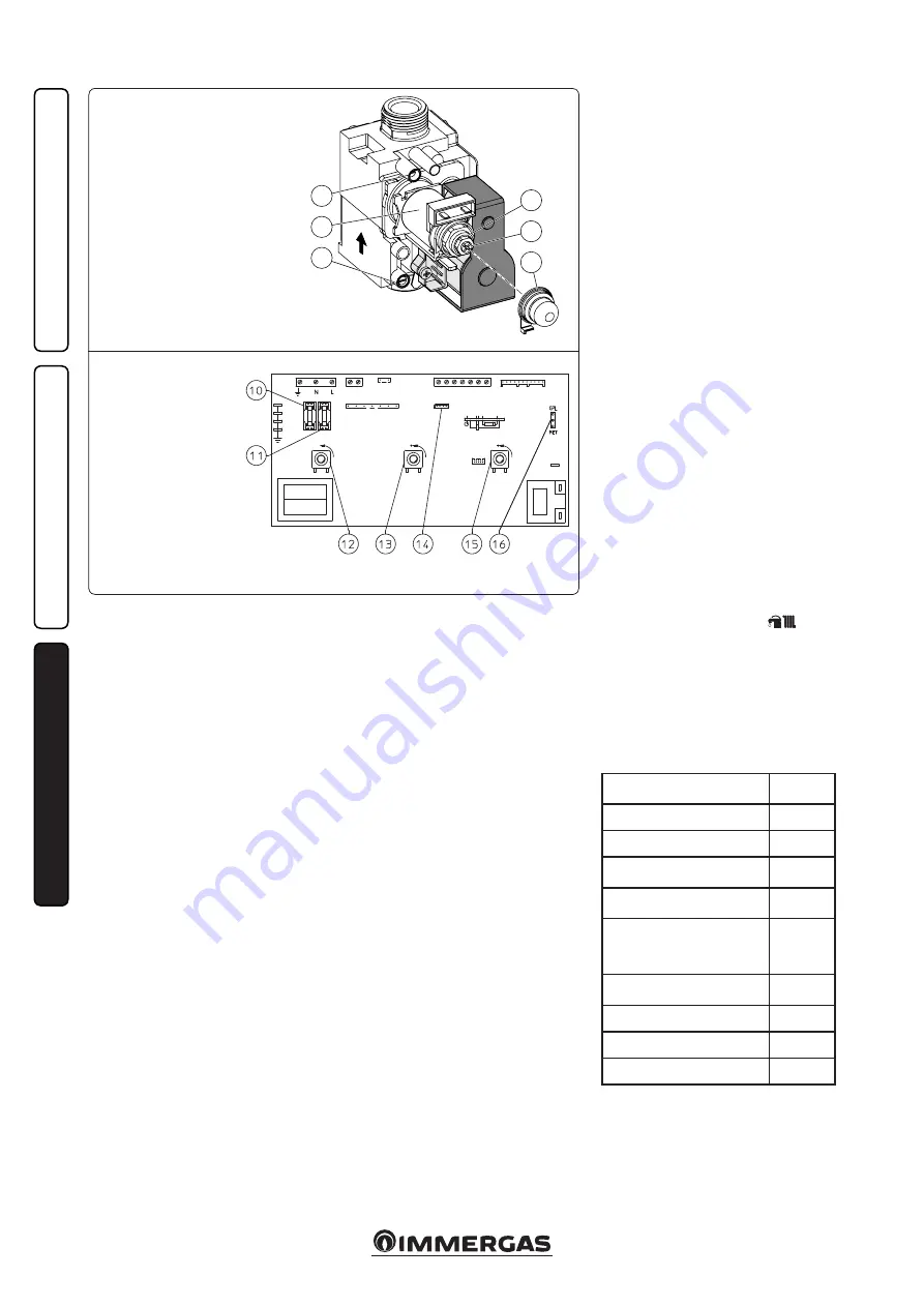
level where it is possible to set the value of the 

SIT 845 gas valve

Key:

  1 -  Coil

  2  -  Minimum power adjustment screws

  3  -  Maximum power adjustment nut

  4  -  Gas valve outlet pressure point

  5  -  Gas valve inlet pressure point

  6  -  Protection hood

Circuit board

  10  -  Line fuse 3.15AF

  11  -  Neutral fuse 3.15AF

  12  -  Main selector switch

  13  -  Domestic water temperature trimmer

  14  -  RS232 computer interface

  15  -  Heating temperature trimmer

  16  -  METHANE L.P.G. gas type selector

Содержание AVIO 24 2 ERP

Страница 1: ...tenance Technician IE 1 038455ENG Wall hung boiler with storage tank open chamber type B and natural draught The European regulation 813 2013 provides that this boiler can be installed only to replace...

Страница 2: ...the regulations in force and principles of good practice In compliance with legislation in force the systems must be designed by qualified professionals within the dimensional limits established by t...

Страница 3: ...s 13 2 7 Boiler shutdown 14 2 8 Restoring heating system pressure 14 2 9 Draining the system 14 2 10 Draining the boiler 14 2 11 Anti freeze protection 14 2 12 Case cleaning 14 2 13 Decomissioning 14...

Страница 4: ...leaks from the hydraulic connections on the contrary the manufacturer cannot be held responsible for any damage caused to the household appliances For the aforementioned reasons we recommend not placi...

Страница 5: ...nger it is recommended to install the polyphosphate proportioner kit in the presence of water whose characteristics can give rise to scale deposits 1 7 ELECTRICAL CONNECTION The Avio 24 2 ErP boiler h...

Страница 6: ...nnot be used for plants divided into zones Electrical connection of the Remote Friend ControlV2 chronothermostat On Off Op tional or Mini The operations described below must be performed after having...

Страница 7: ...eck if the cap is loose Open the radiator air vent valves Close vent valves only when water is delivered Close the filling valve when the boiler pressure gauge indicates approx 1 2 bar N B During thes...

Страница 8: ...fficient to press button 1 once To change operation mode press the button for between 2 to 10 seconds until the current configuration flashing each time the button is pressed all possible functions ar...

Страница 9: ...tal head available to the system with pump at speed 4 A2 Power absorbed by the pump at speed 2 A3 Power absorbed by the pump at speed 3 A4 Power absorbed by the pump at speed 4 Circulator pump absorbe...

Страница 10: ...motorised 7 System filler tap 8 System expansion tank 9 Domestic water probe 10 Stainless steel boiler 11 3 bar safety valve 1 19 BOILER COMPONENTS 12 System emptying tap 13 8 bar safety valve 14 Boi...

Страница 11: ...d dangerous to obstruct the air intake even partially for the ventilation of the room in which the boiler is installed Due to the danger operation is also prohibited in the same room as suction device...

Страница 12: ...anti freeze function is activated 2 6 FAULT AND ANOMALY SIGNALS The Avio 24 2 ERP boiler signals ant anomaly by flashing of one of the LEDs from 4 to 8 or LEDs 1 and 2 coupled to LED 7 On any remote...

Страница 13: ...tioned on Summer or Winter To avoid keeping the system switched on in case of a prolonged absence the system must be drained completely or antifreeze substances added to the heating system water In bo...

Страница 14: ...e appliance combustion products check that there is no backflow of combustion products into the room even during functioning of fans 3 1 HYDRAULIC LAYOUT Key 1 Gas valve 2 Stainless steel coil for boi...

Страница 15: ...out by an authorised company e g Authorised After Sales Technical Assistance Service Smell of gas Caused by leakage from gas circuit pipelines Check sealing efficiency of gas intake circuit Irregular...

Страница 16: ...ases and in an anti clockwise direction it decreases Adjust the boiler minimum thermal input Fig 3 3 N B only proceed after having calibrated the nominal pressure Adjustment of the minimum thermal inp...

Страница 17: ...ng Led 8 Heating switch on delay request from Room thermostat and Remote Friend ControlV2 The boiler is set to switch on immediately after a request In the case of particular plants e g area plants wi...

Страница 18: ...ntion of electrical main electrical switch on boiler system control thermostat intervention domestic water control thermostat intervention Check that the internal system is properly sealed according t...

Страница 19: ...at 0 of O2 at Q Nom Min ppm 177 81 279 115 240 108 Flue temperature at nominal heat output C 101 106 104 Flue temperature at minimum heat output C 74 77 76 METHANE G20 BUTANE G30 PROPANE G31 HEAT POW...

Страница 20: ...2 40 0 57 Heat loss at flue with burner On Off 7 20 0 43 Heating circuit max working pressure bar 3 Heating circuit max working temperature C 90 Adjustable heating temperature C 35 85 Total volume sys...

Страница 21: ...e technical data are shown on the boiler data plate ENG Model Model code Serial Number Check PIN code Type of installation ref CEN TR 1749 Minimum heating capacity domestic Minimum heating capacity he...

Страница 22: ...partial load elmin 0 014 kW Ignition burner energy consumption Pign 0 000 kW In standby mode PSB 0 003 kW Emissions of nitrogen oxides NOX 132 mg kWh For mixed central heating appliances Stated load p...

Страница 23: ...ntary heat pump From fiche of heat pump Solar contribution and Supplementary heat pump Select smaller value Boiler and supplementary heat pump installed with low temperature heat emitters at 35 C From...

Страница 24: ...energy efficiency of the package of products provided far in this fiche may not correspond to its actual energy efficiency once installed in a building as the efficiency is influenced by further facto...

Страница 25: ...contribution From fiche of solar device 1 I 2 1 1 x I 10 x II III I Auxiliary electricity 3 G F E D C B A A A A 27 27 27 28 27 27 27 28 30 30 30 32 33 34 35 36 36 37 38 40 39 50 55 60 65 75 80 85 100...

Страница 26: ...under colder and warmer climate conditions Colder 0 2 x Warmer 0 4 x Declared load profile Solar contribution From fiche of solar device 1 ___ 2 1 1 x ___ 10 x ____ ____ ____ Auxiliary electricity 3...

Страница 27: ......

Страница 28: ...mergas S p A 42041 Brescello RE Italy Tel 0522 689011 Fax 0522 680617 Certified company ISO 9001 This instruction booklet is made of ecological paper Cod 1 038455ENG rev ST 002233 003 04 18 Irlandese...

Отзывы: