background image

5.1.2 Geräte mit Line-Ausgangspegel
Stereo-Geräte mit Line-Ausgangspegel an die sym-
metrischen 6,3-mm-Klinkenbuchsen „LINE-LEFT“
und „LINE-RIGHT“ (28) der Kanäle 13 – 16 an-
schließen. Als zusätzliche Stereo-Line-Eingänge
lassen sich auch die symmetrischen 6,3-mm-Klin-
kenbuchsen „AUX-IN“ (27) oder die asymmetrischen
Cinch-Buchsen „PLAYBACK“ (23) verwenden.

Signalquellen mit Line-Mono-Ausgang an die

Buchsen „LINE“ (30) der Kanäle 1 – 12 anschließen.
Beim Anschluss von Mono-Geräten an die Stereo-
Kanäle 13 – 16 bzw. an den Stereo-Eingang „AUX-
IN“ jeweils nur die obere Buchse „LEFT“ an-
schließen. Das Eingangssignal wird dann intern auf
den rechten und linken Kanal geschaltet.

5.2 Geräte zur Klangbearbeitung einschleifen

Über die 6,3-mm-Klinkenbuchsen „INSERT“ (31) las-
sen sich Geräte zur Klangbearbeitung (wie z. B.
Kompressoren, Noise-Gates) in die Mono-Kanäle
1 – 12 
einschleifen: Das Kanalsignal wird pre-fader
über die Insert-Buchse ausgekoppelt, läuft komplett
über das angeschlossenene Gerät und wird über die-
selbe Buchse wieder zurückgeführt. Das Gerät zur
Klangbearbeitung über ein Y-Kabel, z. B. MCA-202
aus dem Programm von MONACOR, anschließen.

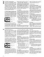
Anschluss des Y-Kabels MCA-202 von MONACOR

Den Stereo-Stecker in die Buchse „INSERT“ (31) ste-
cken. Das Ausgangssignal („Send“) liegt an der Spit-
ze des Stereo-Steckers an, das klanglich bearbeitete
Eingangssignal („Return“) am Ring; am Schaft liegt
die gemeinsame Masse an. Den Mono-Stecker für
das Send-Signal an den Eingang des Gerätes zur

Klangbearbeitung anschließen und den Mono-Ste-
cker für das Return-Signal an seinen Ausgang.

Über die beiden Buchsen „INSERT-RIGHT“ und

„INSERT-LEFT“ (24) ist es auch möglich, ein Gerät
zur Klangbearbeitung (z. B. graphischer Equalizer)
mithilfe zweier Y-Kabel in den rechten und linken
Kanal der Ausgangssumme 
einzuschleifen, noch
vor der Pegelregelung über die Masterfader (19).
Die Buchsen werden wie die Insert-Buchsen in den
Eingangskanälen angeschlossen. Dabei den rech-
ten Ein- und Ausgang des Geräts mit der Buchse
„INSERT-RIGHT“ verbinden und den linken Ein- und
Ausgang mit der Buchse „INSERT-LEFT“.

5.3 Effektgeräte

Der Ausspielweg „AUX“ ist post-fader ausgelegt und
kann damit als Effektweg genutzt werden. Über die-
sen Ausspielweg „AUX“ können Signalanteile aus
den Eingangskanälen ausgekoppelt, von einem Ef-
fektgerät (z. B. Hallgerät) bearbeitet und wieder in
das Mischpult zurückgeführt und auf die Signal-
summe gemischt werden.

Soll stattdessen oder zusätzlich der Ausspielweg

„MON“ als Effektweg verwendet werden, muss er in-
tern von pre-fader (Grundeinstellung ab Werk) auf
post-fader umgestellt werden – siehe dazu Kap. 4.2.

1) Den Eingang des Effektgerätes an den jeweiligen

Send-Mono-Ausgang (26) anschließen:

bei Verwendung von Ausspielweg „AUX“ an
die 6,3-mm-Klinkenbuchse „AUX SEND“,
bei Verwendung von Ausspielweg „MON“ an
die 6,3-mm-Klinkenbuchse „MON SEND“.

2) Den Ausgang des Effektgerätes an den Stereo-

Eingang „AUX-IN“ (27) anschließen (bei einem
Mono-Effektgerät nur die obere Buchse „LEFT“
verwenden) oder an den Line-Eingang eines
freien Eingangskanals.

5.4 Kopfhörer

Beim Abmischen kann sowohl das Mastersignal als
auch das PFL-Signal jedes Eingangskanals über ei-
nen Stereo-Kopfhörer (Impedanz min. 32

) abge-

hört werden. Den Kopfhörer an die 6,3-mm-Klinken-
buchse (17) anschließen. Nähere Informationen zu
der Abhörfunktion finden Sie im Kap. 6.4.

5.5 Aufnahmegeräte

2-Spur-Aufnahme des Mastersignals
Ein 2-Spur-Aufnahmegerät (z. B. Kassettenrecorder,
MiniDisc-Recorder) kann an die Cinch-Ausgangs-
buchsen „RECORD“ (22) angeschlossen werden.
Der Aufnahmepegel wird mit dem Regler „RECORD
LEVEL“ (13) eingestellt und ist zusätzlich von der
Stellung der Masterfader (19) abhängig.

Nach der Aufnahme lässt sich diese über das

Mischpult wiedergeben. Dazu den Ausgang des Auf-
nahmegerätes an die Cinch-Buchsen „PLAYBACK“
(23) anschließen. Das Wiedergabesignal wird mit
dem Regler „PLAYBACK LEVEL“ (15) vor den Mas-
terfadern auf die Ausgangssumme gemischt.

Mehrspuraufnahmen
Für Mehrspuraufnahmen der einzelnen Mono-Ka-
näle 1 – 12 können die Kanalsignale an den asym-
metrischen Ausgangsbuchsen „DIRECT OUT“ (32)
ausgekoppelt werden. Hier liegen die bearbeiteten
Kanalsignale nach den Kanalfadern (7) an. Das
Mehrspur-Aufnahmegerät mit den Direktausgängen
der jeweiligen Kanäle verbinden.

Hinweis: Der Signalabgriffspunkt kann intern für je-

den Direktausgang auch auf pre-equalizer
umgestellt werden (z. B. wenn die Kanal-
signale einem Monitormischpult zugeführt
werden sollen) – siehe dazu Kap. 4.3.

5.6 Verstärker

An den symmetrischen XLR-Buchsen „MAIN MIX
OUTPUT“ (21) steht das mit den Masterfadern (19)
ausgesteuerte Mastersignal zur Verfügung. Hier
kann der Endverstärker für die Saalbeschallung an-
geschlossen werden.

Über den Pre-fader-Ausspielweg „MON“ können

die Musiker ein separat abgemischtes Musiksignal

Eingang
Gerät zur Klangbearbeitung

Ausgang
Gerät zur Klangbearbeitung

RETURN

SEND

RETURN

SEND

rot

schwarz

schwarz

Insert-Buchse
Mischpult

5.1.2 Units with line output level
Connect stereo units with line output level to the
balanced 6.3 mm jacks “LINE-LEFT” and “LINE-
RIGHT” (28) of the channels 13 – 16. The balanced
6.3 mm jacks “AUX-IN” (27) or the unbalanced
phono jacks “PLAYBACK” (23) can also be used as
additional stereo line inputs. 

Connect signal sources with line mono output to

the jacks “LINE” (30) of the channels 1 – 12. When
connecting mono units to the stereo channels 13 – 16
or to the stereo input “AUX-IN”, only connect the up-
per jack “LEFT” respectively. The input signal is then
internally switched to the right and left channels.

5.2 Inserting units for sound processing

Via the 6.3 mm jacks “INSERT” (31), units for sound
processing (e. g. compressors, noise gates) can be
inserted into the mono channels 1 – 12: The chan-
nel signal is taken pre-fader via the insert jack, is
completely routed via the unit connected and re-
turned via the same jack. Connect the unit for sound
processing via a Y cable, e. g. MONACOR MCA-202.

Connection of the MONACOR Y cable MCA-202

Connect the stereo plug to the jack “INSERT” (31).
The output signal (“Send”) is available at the tip of
the stereo plug, the input signal (“Return”) pro-
cessed in sound is available at the ring; the common
ground is available at the body. Connect the mono
plug for the send signal to the input of the unit for 
sound processing and the mono plug for the return
signal to its output.

The two jacks “INSERT-RIGHT” and “INSERT-

LEFT” (24) also allow insertion of a unit for sound
processing (e. g. graphic equalizer) into the right
and left channels of the master outpu
t by means
of two Y cables, even ahead of the level control via
the master faders (19). The jacks are connected like
the insert jacks in the input channels. For this pur-
pose, connect the right input and output of the unit to
the jack “INSERT-RIGHT” and the left input and ou-
tput to the jack “INSERT-LEFT”.

5.3 Effect units

The send way “AUX” is designed as a post-fader
way and can thus be used as an effect way. Via this
send way “AUX”, signal parts can be taken from the
input channels, processed by an effect unit (e. g. re-
verberation unit), returned to the mixer and mixed to
the master signal. 

If the send way “MON” is to be used as an effect

way instead or additionally, it must be modified inter-
nally from pre-fader (basic adjustment in the factory)
to post-fader – see chapter 4.2.

1) Connect the input of the effect unit to the corre-

sponding send mono output (26):

when using the send way “AUX”, connect it to
the 6.3 mm jack “AUX SEND”, 
when using the send way “MON”, connect it to
the 6.3 mm jack “MON SEND”.

2) Connect the output of the effect unit to the stereo

input “AUX-IN” (27) [in case of a mono effect unit,
only use the upper jack “LEFT”] or to the line
input of an unconnected input channel.

5.4 Headphones

When mixing, both the master signal and the PFL
signal of each input channel can be monitored via
stereo headphones (minimum impedance 32

).

Connect the headphones to the 6.3 mm jack (17).
Detailed information concerning the monitoring fea-
ture can be found in chapter 6.4.

5.5 Recorders

2-track recording of the master signal
A 2-track recorder (e. g. cassette recorder, minidisk
recorder) can be connected to the phono output
jacks “RECORD” (22). The recording level is adjust-
ed with the control “RECORD LEVEL” (13) and ad-
ditionally depends on the position of the master 
faders (19).

The recording made can be replayed via the 

mixer. For this purpose, connect the output of the re-
corder to the phono jacks “PLAYBACK” (23). The re-
play signal is mixed to the master output ahead of
the master faders with the control “PLAYBACK LEV-
EL” (15).

Multitrack recordings
For multitrack recordings of the individual mono
channels 1 – 12, the channel signals can be taken at
the unbalanced output jacks “DIRECT OUT” (32).
This is where the processed channel signals are
available after the channel faders (7). Connect the
multitrack recorder to the direct outputs of the corre-
sponding channels. 

Note: The signal take-off point can also be inter-

nally modified to pre-equalizer for each direct
output (e. g. if the channel signals are to be
fed to a monitor mixer) – see chapter 4.3.

5.6 Amplifier 

The master signal controlled to an optimum level
with the master faders (19) is available at the
balanced XLR jacks “MAIN MIX OUTPUT” (21). This
is where the power amplifier for the PA application in
halls can be connected.

The pre-fader send way “MON” allows the musi-

cians on stage to receive a separately mixed music
signal from a monitoring system. Connect the power
amplifier of the monitoring system to the unbalanced
6.3 mm jack “MON SEND” (26). 

insert jack
mixer

input
unit for sound processing

output
unit for sound processing

RETURN

SEND

RETURN

SEND

red

black

black

8

GB

D

A

CH

Содержание MMX-162

Страница 1: ...E AUDIO 16 CANAUX MIXER AUDIO A 16 CANALI MMX 162 Best Nr 20 1960 BEDIENUNGSANLEITUNG INSTRUCTION MANUAL MODE D EMPLOI ISTRUZIONI PER L USO GEBRUIKSAANWIJZING MANUAL DE INSTRUCCIONES INSTRUKCJA OBSŁUGI SIKKERHEDSOPLYSNINGER SÄKERHETSFÖRESKRIFTER TURVALLISUUDESTA ...

Страница 2: ...lysningerne for at undgå forkert betjening og for at be skytte Dem og Deres apparat mod skade på grund af for kert brug Sikkerhedsoplysningerne finder De på side 32 Förskrift Vi önskar dig mycket nöje med din nya enhet från img Stage Line Läs gärna säkerhetsinstruktionerna innan du använder enheten Genom att följa säkerhetsinstruk tionerna kan många problem undvikas vilket annars kan skada enheten...

Страница 3: ...0 20 30 0 10 0 10 L R PK PFL 10 5 0dB 5 10 HI 12k LO 45Hz AUX MON BAL 16 30 20 LEFT RIGHT 15 12 9 6 3 0dB 3 6 9 12 15 20 0 10 0 10 0 10 0 10 0 10 0 10 L R PHONES AUX IN AUX SEND MON SEND MAIN MIX 10 5 0dB 5 30 20 10 5 0dB 5 30 20 POWER PHANTOM POWER 48V POWER RECORD LEVEL PLAYBACK LEVEL MMX 162 16 CHANNEL PRO AUDIO MIXER GAIN GAIN GAIN GAIN GAIN GAIN GAIN GAIN GAIN GAIN GAIN MIC 12 60dB 40 20 30 0...

Страница 4: ... 48 V 25 eingeschaltet wurde 13 Pegelregler für den Aufnahmeausgang RE CORD 22 14 Summenregler jeweils für den Ausspielweg AUX und den Ausspielweg MON Please unfold page 3 Then you can always see the opera ting elements and connections described Contents 1 Operating Elements and Connections 4 2 Safety Notes 6 3 Applications 6 4 Modification of the Input Channels 6 4 1 Switching off the phantom pow...

Страница 5: ...ein da diese beschädigt werden könnten Vorsicht Den Schalter nur bei ausgeschaltetem Misch pult betätigen um Schaltgeräusche zu vermei den Bitte beachten Sie auch den Vorsichts hinweis der Position 29 14 Master controls respectively for the send way AUX and the send way MON 15 Level control for the input PLAYBACK 23 16 Level control for headphones connected to the jack 17 below 17 6 3 mm jack for ...

Страница 6: ...ktrischen Schlages Außerdem erlischt beim Öffnen des Geräts jeglicher Garantieanspruch 2 Safety Notes This unit corresponds to the directive for electro magnetic compatibility 89 336 EEC and to the low voltage directive 73 23 EEC Please observe the following items in any case The unit is suitable for indoor use only Protect it against dripping water and splash water high air humidity and heat admi...

Страница 7: ...so the nuts below the operating elements at the channel to be modified Also unscrew the fader if required 5 It is now possible to carefully remove the PCB Take care not to tear off any connection cable 6 Perform the desired modifications for the channel according to chapters 4 1 to 4 3 7 Reassemble the mixer Prior to fastening the screws to join the front panel and the bottom part of the housing m...

Страница 8: ... Musiker ein separat abgemischtes Musiksignal Eingang Gerät zur Klangbearbeitung Ausgang Gerät zur Klangbearbeitung RETURN SEND RETURN SEND rot schwarz schwarz Insert Buchse Mischpult 5 1 2 Units with line output level Connect stereo units with line output level to the balanced 6 3 mm jacks LINE LEFT and LINE RIGHT 28 of the channels 13 16 The balanced 6 3 mm jacks AUX IN 27 or the unbalanced phon...

Страница 9: ...stärke nie sehr hoch ein Hohe Laut stärken können auf Dauer das Gehör schädigen Das menschliche Ohr gewöhnt sich an große Laut stärken und empfindet sie nach einiger Zeit als nicht mehr so hoch Darum eine hohe Lautstärke nach der Gewöhnung nicht weiter erhöhen Note The following modifications of the send ways may be performed internally see chapter 4 2 a The send way MON can also be modified to pr...

Страница 10: ...the send ways a If a send way is used as an effect way it should be designed post fader signal is taken after the channel faders The send way AUX is factory set to post fader b If a send way is used as a monitor way it should be designed pre fader signal is taken ahead of the channel faders The send way MON is fac tory set to pre fader If required the send way AUX can be modified to pre fader and ...

Страница 11: ...Sig nalunterschied zwischen den Leitungen weiterverstärkt wird Gegenteil asymmetrisch Vorhören Das Signal eines Eingangskanals wird pre fader über einen Kopfhörer abgehört Auf diese Weise ist es mög lich eine Tonquelle auch bei zugezogenem Kanalfader zu hören z B um sie zum gewünschten Zeitpunkt einzublenden XLR Geschütztes Warenzeichen für professionelle Steckver bindungen XLR Stecker und Buchsen...

Страница 12: ... V 25 13 Potentiomètre de réglage de niveau pour la sor tie d enregistrement RECORD 22 Vi preghiamo di aprire completamente la pagina 3 Così ve drete sempre gli elementi di comando e i collegamenti de scritti Indice 1 Elementi di comando e collegamenti 12 2 Avvertenze di sicurezza 14 3 Possibilità d impiego 14 4 Modifica dei canali d ingresso 14 4 1 Disattivare l alimentazione phantom per singoli ...

Страница 13: ...z l interrupteur que si la table de mixa ge est éteinte pour éviter les bruits forts lors de l allumage Respectez le conseil dans la posi tion 29 15 Regolatore livello per l ingresso PLAYBACK 23 16 Regolatore livello per una cuffia collegata con la presa sottostante 17 17 Presa jack 6 3 mm per il collegamento di una cuf fia stereo impedenza min 32 Ω a per ascoltare il segnale master alle prese MAI...

Страница 14: ...s que par un technicien spécialisé et qualifié Attention L appareil est alimenté par une tension dange reuse en 230 V Ne touchez jamais l intérieur de l appareil car en cas de mauvaise manipulation vous pouvez subir une décharge électrique En ou tre l ouverture de la table de mixage rend tout droit à la garantie caduque 2 Avvertenze di sicurezza Quest apparecchio è conforme alle direttive CE 89 33...

Страница 15: ...1 3 ON CONN4 CONN3 1 3 OFF 1 3 ON CONN3 4 1 Disattivare l alimentazione phantom per singoli canali canali mono o attivarla canali stereo L alimentazione phantom 48 V per i canali mono 1 12 è attivabile centralmente con l interruttore PHANTOM POWER 48 V 25 Tuttavia è possi bile disattivarla per ogni canale singolarmente se si devono collegare sia microfoni asimmetrici che microfoni con alimentazion...

Страница 16: ... uscita LINE Collegare gli apparecchi stereo con livello d uscita Line con le prese jack 6 3 mm simmetriche LINE LEFT e LINE RIGHT 28 dei canali 13 16 An che le prese jack 6 3 mm simmetriche AUX IN 27 o le prese RCA asimmetriche PLAYBACK 23 possono essere utilizzate come ingressi supplemen tari stereo Line Le sorgenti di segnali con uscita mono Line si col legano alle prese LINE 30 dei canali 1 12...

Страница 17: ...lus comme tels au bout d un certain temps Nous vous conseillons donc de régler le vo lume et de ne plus le modifier Collegare l amplificatore finale dell impianto di moni toraggio con la presa jack 6 3 mm asimmetrica MON SEND 26 N B Internamente si possono eseguire le seguenti modi fiche delle vie di disaccoppiamento vedi cap 4 2 a La via di disaccoppiamento MON può essere cambiata a pre equalizer...

Страница 18: ... impostata dalla fab brica a post fader b Se una via di disaccoppiamento viene usata come via di monitoraggio dovrebbe essere previ sta come pre fader punto di disaccoppiamento del segnale a monte dei fader dei canali La via di disaccoppiamento MON è impostata dalla fabbrica a pre fader Se necessario la via di disacoppiamento AUX può essere cambiata a pre fader e la via MON a pre equalizer o post ...

Страница 19: ...corsivo sono spiegati con i relativi lemmi Alimentazione phantom l alimentazione di tensione per microfoni a condensatore che è presente ai contatti 1 massa e 2 3 positivo di prese XLR a 3 poli Il segnale del microfono non viene influenzato poiché solo il positivo dell alimentazione si trova sulle linee simmetriche contatti 2 e 3 asimmetrico asimm nella trasmissione asimmetrica dei segnali il segn...

Страница 20: ...voeding van 48 V voor de microfooningangen 29 van de monoka nalen met de schakelaar PHANTOM POWER 48 V 25 werd ingeschakeld Abrir el libro página 3 de manera a visualizar los elementos y las conexiones Índice 1 Elementos y conexiones 20 1 1 Parte delantera 20 1 2 Parte trasera 21 2 Consejos de seguridad y utilización 22 3 Posibilidades de utilización 22 4 Modificaciones de los canales de entrada 2...

Страница 21: ...crofooningangen van de mono kanalen 1 12 met een fantoomvoeding van 48V Opgelet Om luide schakelploppen te vermijden ge bruikt u de schakelaar uitsluitend bij uitgescha keld mengpaneel Lees ook de veiligheidsop merking van pos 29 14 Potenciómetro master respectivamente para la vía AUX y la vía MON 15 Potenciómetro de nivel para la entrada PLAY BACK 23 16 Potenciómetro de nivel para el auricular co...

Страница 22: ...okken Bovendien vervalt elke garantie bij het eigenhandig openen van het toestel 2 Consejos de seguridad y utilización Este aparato cumple la normativa europea 89 336 CEE relacionada con la compatibilidad electroma gnética y con normativa 73 23 CEE relacionada con los aparatos de baja tensión Respete escrupulosamente los puntos siguientes El aparato está fabricado solo para una utilización en inte...

Страница 23: ...chadigd PRE EQ JP3 POST FADER POST FADER JP2 PRE FADER PRE EQ PRE FADER JP1 POST FADER 1 3 ON CONN4 CONN3 1 3 OFF 1 3 ON CONN3 4 1 Desconexión de la alimentación phantom para canales individuales canales mono conexión canales estéreo Puede conmutar la alimentación phantom 48 V de los canales mono 1 12 de manera central con el interruptor PHANTOM POWER 48 V 25 puede cortarse separadamente para cada...

Страница 24: ...e ongebalanceerde 6 3 mm jack MON SEND 26 ingang apparaat voor de klankbewerking uitgang apparaat voor de klankbewerking RETURN SEND RETURN SEND rot schwarz schwarz insert jack mengpaneel 5 1 2 Aparatos con nivel de salida línea Conecte los aparatos estéreo con nivel de salida lí nea en las tomas jack 6 35 simétricas LINE LEFT y LINE RIGHT 28 de los canales 13 16 Como entradas estéreo línea suplem...

Страница 25: ...geluidsinstallatie en dat van de hoofdtelefoon nooit zeer hoog in Langdurige blootstelling aan hoge volumes kan het gehoor be schadigen Het gehoor raakt aangepast aan hoge volumes die na een tijdje niet meer zo hoog lijken Verhoog daarom het volume niet nog meer nadat u er gewoon aan bent geraakt Nota las modificaciones siguientes de las vías pueden efectuarse en interno vea capítulo 4 2 a la vía ...

Страница 26: ...a como post fader punto de tomar la señal después de los faders de los canales La vía AUX se regula en fábrica en post fader b Si se utiliza una vía como vía monitor debería estar configurada como pre fader punto de to mar la señal antes de los faders de los canales La vía MON se regula en fábrica en pre fader Si es necesario puede regular la vía AUX en pre fader y la vía MON en pre ecualizador o ...

Страница 27: ... stekkerver bindingen XLR stekkers en jacks zijn speciaal voor gebalan ceerde signaaloverdracht uitgevoerd 8 Glosario Las palabras en itálica están explicadas seguidamente Alimentación phantom una tensión de alimentación para los micros a condensadores que está presente a los contactos 1 masa y 2 3 polo positivo de las tomas XLR 3 polos La señal del micro no está influenciada porque solo el polo p...

Страница 28: ...ądze nia rejestrującego RECORD 22 14 Regulatory poziomów sygnałów wyjść AUX oraz MON 15 Regulator poziomu sygnału wejściowego PLAY BACK 23 16 Regulator poziomu sygnału słuchawek podłą czonych do gniazda 17 znajdującego się poniżej 17 Gniazdo do podłączania słuchawek stereo mini malna impedancja 32 Ω a do monitorowania sygnału podawanego na gniazda MAIN MIX OUTPUT 21 jeżeli żaden z przycisków PFL 6...

Страница 29: ... W razie po trzeby należy również odkręcić potencjometr Uwaga Następujące modyfikacje wymagają wiele wysiłku Ponieważ niezbędne jest wyciągnięcie obwodów poszczególnych kanałów mogą być one dokony wane jedynie przez odpowiednio wyszkolony personel Uwaga Urządzenie zasilane jest prądem elektrycznym o na pięciu 230V Wszelkie naprawy powinny być prze prowadzane tylko przez osoby do tego upoważnione N...

Страница 30: ... wyjściowego jack 6 3 mm MON SEND 26 wejście urządzenia do obróbki dźwięku wyjście urządzenia do obróbki dźwięku RETURN SEND RETURN SEND czerwony czarny czarny gniazdo INSERT miksera Uwaga Poprzez modyfikację torów AUX można dokonać następujących zmian patrz rozdział 4 2 a Tor MON może być zmodyfikowany do pre equa lizer tzn sygnał wychodzi przed korektorem b Tor AUX może być modyfikowany z post f...

Страница 31: ...nich wartościach poziomu sygnału Jakkolwiek sygnał może być zbyt słaby lub zbyt silny dla kolejnego podłączonego urzą dzenia W tym wypadku należy go odpowiednio zwiększyć lub zmniejszyć 6 4 Monitorowanie za pomocą słuchawek Za pomocą słuchawek stereo podłączonych do gniazda 17 można monitorować jeden kanał kilka kanałów lub wyjście główne miksera PFL pre fa der listening W takiej sytuacji wskaźnik...

Страница 32: ...l Varmen der udvikles i enheden skal kunne slippe ud ved hjælp af luftcirkulation Enhedens ventila tionshuller må derfor aldrig tildækkes Undlad at indføre noget i ventilationshullerne Dette kan forårsage fare for elektrisk stød Tag ikke enheden i brug og tag straks stikket ud af stikkontakten i følgende tilfælde 1 hvis der er synlig skade på enheden eller net kablet 2 hvis der kan være opstået sk...

Страница 33: ...indication PFL LED PK PFL indication Peak R Peak L R AUX MON PFL CONTROL MON SEND OUTPUTS AUX SEND MON SEND AUX SEND AUX SEND MON SEND INSERT RIGHT RIGHT FADER OUTPUT MAIN MIX RIGHT R INSERT LEFT LEFT FADER OUTPUT MAIN MIX LEFT L Send L Return L Send R Return R RECORD LEFT RECORD RIGHT VU METER 0dB 1 23V 20 15 12 9 6 3 0dB 3 6 9 12 15 MASTER OUTPUT OUTPUT PHONES Master L R PFL PFL PHONES LEVEL PFL...

Страница 34: ...Copyright by MONACOR INTERNATIONAL GmbH Co KG Bremen Germany All rights reserved A 0156 99 01 11 2003 ...

Отзывы: