


Page 14
Operation Manual
B
Hardware
B.1
Device Overview
B.1.1
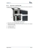
Front Side Elements
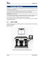
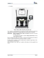
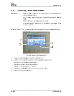
Picture 1: Elements of the Bookeye 4-V1A C35
Some of the major components of the scanner have been identified in the above picture.
These components are referenced in this operation manual.
The main hardware elements are:
1. Camera head. The camera head contains the camera, the red line laser, and the lamps.
2. TFT flat screen. Shows the scanned image. All modifications of an image, e.g. color
mode or scan size, will be displayed immediately on the TFT flat screen.
3. Glass plate. Flattens the curvature of the book binding and ensures a continuous focus
level. The glass plate opens and closes motor-powered.
4. V-shaped b
ook cradle. Can be fixed in “V” position or lie in a flat position. The opening
angle of the book cradle plates in V-position is 140 degrees.
5. Motor-powered lifting column.
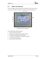
6. Dual display to set the scan parameters (upper touchscreen) and to control the lifting
columns of the book cradle plates, the glass plate, and the automated scan modes
(lower touchscreen).
Содержание Bookeye 4
Страница 1: ...V1A C35 Operation Manual...
Страница 2: ...File ArbVers_BE4 V1A C35_OperationManual_2015 KW45 docx Art Nr BE4 V1 C35 MAN EN...
Страница 10: ...Page 10 Operation Manual...


