Operating manual - English
ECODRILL 2000 CODE
29
9.4
Replacing the electronic board - the keypad
If the keypad (K) is not working properly, replace the internal electronic board or the keypad unit.
Note: the letters in brackets refer to fig.4, page 10.
9.4.1
Replacing the circuit board
Note: before carrying out any operations, disconnect the machine from the mains.
Replace the circuit board in the way described below:
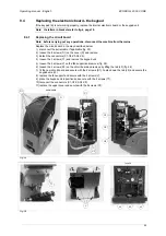
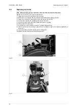
1) disconnect the serial cable, if applicable (fig. 25).
2) loosen the 8 screws (D1) on the cover (D) and remove.
3) detach the connectors (C1-C2-C3-C4-C5).
4) loosen the 2 screws (T1) and remove the keypad unit.
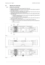
5) loosen the 4 screws (V) on the fan support and remove (fig. 26).
6) loosen the 4 screws (S1) on the circuit board and remove by lifting the tab (L2) (fig. 26).
7) fit the new circuit board and secure with the 4 screws (S1). Fasten down the tab (L2) and secure the
keypad wire (L3).
8) replace the fan support and secure with the 4 screws (V).
9) place the keypad unit in position and secure with the 2 screws (T1).
10) reconnect the connectors (C1-C2-C3-C4-C5).
11) replace the upper cover and secure with the 8 screws (D1).
Fig. 25
Fig. 26
D1
D
C1
C2
C3
C4
C5
serial cable
V
T1
S1
fuse 2A
L3
L2

