Operating manual - English
ECODRILL 2000 CODE
27
9
MAINTENANCE
WARNING:
for repairs or replacement of parts for maintenance, the ‘CE’ mark is guaranteed only if original
spare parts provided by the manufacturer are used.
Although the ECODRILL 2000 CODE key-cutting machine does not require special maintenance, it is
advisable to check and, if necessary, replace the parts subject to wear, such us: the belt, the lamp.
Replacement is simple and can be carried out by the operator.
CLEANING
: keep the carriage and clamps free of chippings from the cutting operations by cleaning with
a dry brush.
WARNING:
DO NOT USE COMPRESSED AIR!
WARNING:
for normal servicing of the burnished mechanical parts, we recommend using lubricants or
protective oil, e.g. WD40 or similar. Do not apply to the parts used for electrical contact (clamps,
decoders, cutters, gauging templates, etc.). Do not contaminate the electronic parts with the oil.
Before starting any type of maintenance (checks or replacements), read the instructions below:
•
never carry out maintenance or servicing with the machine switched on.
•
always remove the mains plug.
•
follow all the instructions in the manual to the letter.
•
use original spare parts.
9.1
Replacing the belt and adjusting tension
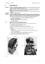
If the upper part of the machine vibrates, check the tension on the belt, as described below:
1) turn off the master switch and remove the mains plug.
2) disconnect the serial cable, if applicable.
3) loosen the 8 screws (D1) and remove the upper casing (D) (fig.22).
4) loosen (but do not remove) the four socket head screws (F1) securing the motor.
5) tension:
- increase belt tension by pushing the motor towards the back of the machine.
6) replacement:
- loosen the belt (F2) by pushing the motor slightly towards the tracer point and cutting tool.
- remove the belt and replace.
- tighten the tension by pushing the motor towards the back of the machine.
7) secure the motor by tightening the four socket head screws (F1).
8) replace the upper casing (D) and secure with the screws (D1).
Fig. 22
D1
D
serial cable
F1
F2

