6
4. Input Signal Connection
4-1. NTSC/PAL Analog Video
: Connect to the Video input.
4-2. NTSC/PAL Analog S-Video
: Connect to the S-Video input.
4-3. RGB or Y.Pb.Pr. Analog Signals (BNC Connector)
:
For G/Y signal : Connect to a component G/Y input.
For B/Pb.signal: Connect to a component B/Pb.input.
For R/Pr.signal : Connect to a component R/Pr. input.
For Sync signal: Connect to a component Sync input.
4-4. PC Analog signal
: Connect to a PC input of D-Sub 15 pin connector.
4-5. PC Digital signal
: Connect to a DVI input.
4-6. Remote Connection
:
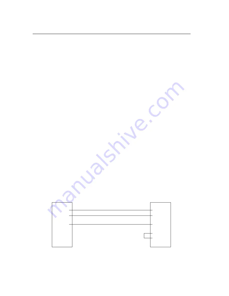
Remote control is possible with a remote control signal feed. The unit provides
a 9 pin D-sub connector on a rear panel. The connection is simple, but please
note that No.7 and No.8 pins of an input connector should be bridged.
And please consult your dealer or supplier for details.
1.
2.TXD
3.RXD
4.
5.GND
6.
7.
8.
9.
1.
2.RXD
3.TXD
4.
5.GND
6.
7.RTS
8.CTS
9.
LCD Monitor Rear Side/
D-SUB 9 pins Connector
The Outside PC/D-SUB
9 pins Connector
* The PC side looping connects 7 pins and 8 pins.


