10
6 Installation
►
Mount the unit on a DIN rail in a housing protected against dust and humidity
(min� IP54 - degree of soiling 2)�
7 Electrical connection
►
Use 60/75°C copper conductors only�
7.1 Supply voltage
The external supply unit must have a safe separation� In case of a fault the
voltage can exceed the value of 60 V DC for a maximum of 200 ms, but
must not exceed the value of 120 V DC�
►
Connect supply voltage
Manual reset
For safety reasons the unit can only be restarted by
separation from the supply voltage in case of a fault�
It is thus recommended to install a RESET switch in
series with the L+ circuit�
After power on or a RESET the unit carries out self diagnostic functions� After this
self diagnosis the unit is ready for operation�
Содержание G1501S
Страница 1: ...706199 00 04 2012 Original operating instructions Safety relay with relay outputs G1501S UK ...
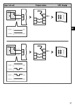
Страница 16: ...16 Input circuit Output status LED display ...
Страница 17: ...17 UK Input circuit Output status LED display ...
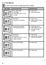
Страница 26: ...26 LED display Cause of the fault Troubleshooting Short circuits Check wiring ...
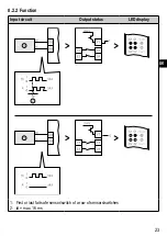
Страница 29: ...29 UK Input circuit Output status LED display 1 Electronic fail safe sensor 1 2 Electronic fail safe sensor 2 ...
Страница 34: ...34 8 4 2 Function Input circuit Output status LED display N O contact activated ...
Страница 35: ...35 UK Input circuit Output status LED display 1 Electronic fail safe sensor 1 2 Electronic fail safe sensor 1 ...
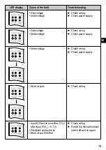
Страница 44: ...44 LED display Cause of the fault Troubleshooting Short circuits Check wiring ...
Страница 49: ...49 UK ...


