ifm
Supplementary device manual Interface CANopen in the AS-i controllerE
Function
The fieldbus modules
74
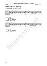
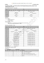
Command 31, 16#1F
– one-time execution of the "Extended safety monitor protocol" in the
"Safety at Work" monitor.
Request from the host >> controllerE:
Word no.
Bit
15
14
13
12
11
10
9
8
7
6
5
4
3
2
1
0
1
0
0
0
user ID
command number = 21 (16#1F)
2
reserved = 00
reserved = 00
3
subcommand = 0
0
0
0
AS-i slave address
4…16
not used
not used
17
field number = 0
data length = 0
18
not used
not used
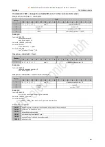
Example:
1st word: 16#071F
command number 16#1F,
user ID changes to 7
2nd word: 16#0000 (reserved)
3rd word: 16#001E
subcommand 0 = one-time execution of the "Extended safety monitor protocol"
"Safety at work" monitor with the address 30 =16#1E
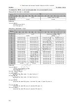
Response controllerE >> host:
Word no.
Bit
15
14
13
12
11
10
9
8
7
6
5
4
3
2
1
0
1
0
0
0
user ID
reflected command number = 16#1F
2
reserved
reserved
3
subcommand = 0
0
0
0
AS-i slave address
4
LEDs OSSD 1
LEDs OSSD 2
data call 1
data call 0
5
OSSD2 not green
OSSD1 not green
6
1st colour output circuit 1
1st module address output circuit 1
7
2nd colour output circuit 1
2nd module address output circuit 1
8
3rd colour output circuit 1
3rd module address output circuit 1
9
4th colour output circuit 1
4th module address output circuit 1
10
5th colour output circuit 1
5th module address output circuit 1
11
6th colour output circuit 1
6th module address output circuit 1
12
1st colour output circuit 2
1st module address output circuit 2
13
2nd colour output circuit 2
2nd module address output circuit 2
14
3rd colour output circuit 2
3rd module address output circuit 2
15
4th colour output circuit 2
4th module address output circuit 2
16
5th colour output circuit 2
5th module address output circuit 2
17
6th colour output circuit 2
6th module address output circuit 2
18
field number = 0/1
0
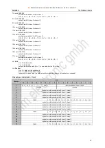
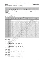
Description of the different fields:
Word no. 4:
LEDs OSSD 1
LEDs OSSD 2
Meaning
15
14
13
12
11
10
9
8
0
0
0
0
0
0
0
0
green = contacts of the output circuits closed
0
0
0
1
0
0
0
1
yellow = start-up / restart disable active
0
0
1
0
0
0
1
0
yellow flashing or red = contacts of the output circuits open
0
0
1
1
0
0
1
1
red flashing = error on the level of the monitored AS-i components
0
1
X
X
0
1
X
X
reserved

