background image


20030516                                                                  

User’s Manual


STAR FINGER007


1 DOOR ACCESS CONTROLLER WITH FINGERPRINT


USER’S MANUAL 


Access Controller 

Rev. V1.0 


Содержание Star Finger007

Страница 1: ...20030516 User s Manual STAR FINGER007 1 DOOR ACCESS CONTROLLER WITH FINGERPRINT USER S MANUAL Access Controller Rev V1 0 ...

Страница 2: ...BATTERY S W 5 4 SYSTEM INITIALIZATION Extra Reader Port 5 4 WIRING 5 4 1 POWER 5 4 2 INPUT CONNECTIONS 5 4 3 OUTPUT CONNECTIONS 5 4 4 READER CONNECTIONS Extra Reader 6 COMMUNICATIONS Page 17 6 1 RS232 COMMUNICATION PORT CONNECTION 6 2 RS 422 COMMUNICATION PORT CONNECTION 6 2 1 RS 422 COMMUNICATION STANDALONE 6 2 2 RS 422 COMMNUNICATION MULTIPLE FINGER007 CONNECTIONS 6 3 DIAL UP MODEM 6 4 TCP IP CO...

Страница 3: ...GER007 9 SETTING CHANGES Page 26 9 1 SETUP MENU F1 9 2 SETUP MENU F2 9 3 SETUP MENU F3 9 4 SETUP MENU F4 APPENDIX Page 50 A THE RELATION BETWEEN INPUT AND OUTPUT DEFAULT B TROUBLE SHOOTING WARRANTY AND SERVICE Page 56 TEMPLATE Page 57 ...

Страница 4: ... not operate normally Do NOT set this product near heaters or any thing that produces heat There may be a risk of fire Be ALWAYS careful not to short circuit any part of the circuitry with tools like a screwdriver in hand There may be a risk of fire or heavy damage of the unit ON MAINTENANCE Do NOT use any kind of liquid for cleaning There may be a risk of electric shock fire or heavy damage of th...

Страница 5: ...as been spilt or sprayed onto the product In this case cut the power off first B The product seems to be operating abnormally C The unit exhibits a distinct change in performance D The unit has fallen to be broken down or damaged on its case The cost of repairing can be charged for troubles due to the improper handling or negligence of users or the operator ...

Страница 6: ...els of ID verification Any combination of prox PIN and biometric may be used and different verification levels can be custom programmed for each user or user group Four independent input ports can be utilized for a wide variety of controls including exit buttons door contacts PIR sensors and fire detection equipment Actions to be taken and time settings can be programmed with the front keypad or v...

Страница 7: ...r Communication port RS232 RS422 up to 32 channels selectable 4800 9600 Default 19200 38400bps communication speed Input Output 4 Input ports DC12V 20mA 2 Relay Output ports DC12V FORM C Relay 2A max 2 TTL Output ports DC5V 20mA Keypad 16 Keypad Back lighting LCD 1 x LCD module 2Lines x 16ch 65 6 x 13 8mm view area Light source LED finger unit Mounting Wall mounted Color Dark pearl gray Material P...

Страница 8: ... connected to host PC the integrated keypad and LCD display module can also be used for the entire programming process manually Anti Pass Back Using an additional proximity reader foe exiting the Anti Pass Back mode can be set Anti Pass Back mode prevents any entry or exit when the registered user did not properly followed one entry and one exit by the Anti Pass Back rule APB only allowed exit for...

Страница 9: ... be generated until the door is closed Duress Alarm You can select Duress Mode enable or disable If you select Duress Mode enable in case of Duress enter the 2 digit Duress Password and press ENT and open the door using general process If you registered ID then Duress Output will be generated and alarm event will be sent to the host PC 1 N Certification IDENTIFICATION You can certify using the fin...

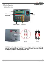
Страница 10: ...verse side Template hole for the backup battery connection Before the FINGER007 installation it needs to be connected before H W initialize so that backup battery can retain the memory during power failure LCD 16 Numeric keypad Fingerprint Input window 3 LED showing system status Function Key BAT connection S W OFF state ON state ...

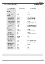
Страница 11: ...arm Relay NC NC 2 Purple with White stripe Alarm Relay NO NO 2 Purple TTL Output1 TTL1 Orange with White stripe TTL Output2 TTL2 Brown with White stripe INPUT Exit Button EXIT Orange Door Sensor CONTACT Yellow with Red stripe Aux Input 1 IN1 Green Aux Input 2 IN2 Green with White stripe EXTRA READER Wiegand Data0 DATA0 Pink Wiegand Data1 DATA1 Cyan RS232 INTERFACE RS232 TX TXD Black with White str...

Страница 12: ...verall foil braid shield PVC insulation and jacket 14 7 ohms 1000 feet about 300meter CONDUIT The FINGER007 does not normally require conduit However some location may require conduit for wire protection Check installation requirements and specifications for your site COMMUNICATIONS WIRING FINGER007 communication is required for using twisted pair wires RS232C 15 meters RS422 1200 meters POWER WIR...

Страница 13: ...TIONS Before mounting the STAR FINGER007 unit to the Wall Mount bracket an operational test of the unit should be completed because the locking pins will lock the unit to the Wall Mount Removing the unit from the Wall Mount bracket after it has been snapped in place may cause damage to the bracket and prevent reattachment Insert 5 O Rings to the Wall Mount as indicated then run the cable from the ...

Страница 14: ... W initialization before the FINGER007 installation Of V4 70 or higher you must connect battery backup S W in reverse side before H W initialization You can H W initialize using extra reader port First turn off the system power and connect 3 wires pink cyan and black GND and turn on the system power Then you can hear Initialize beep and display picture 1 If you want H W initializing enter key 1 2 ...

Страница 15: ...wire Auxiliary Input Connection Applied IN1 IN2 Connect one wire from an Auxiliary Input Device to one of the IN1 Green wire IN2 Green with White stripe Connect the other wire from the Auxiliary Input Device to GND Black wire Figure INPUT DEVICES CONNECTION 5 4 3 OUTPUT CONNECTIONS Door Lock Power Fail Safe Connection Relay 1 Connect COM port of Relay 1 to 12V Connect NC port of Relay 1 to wire of...

Страница 16: ...re of the Proximity Reader to GND Black wire Connect Data 0 wire of the Proximity Reader to DATA0 Pink wire Connect DATA 1 wire of the Proximity Reader to DATA1 Cyan wire Compatible Readers Extra Reader FINGER007 iPFINGER007 Standard 26bit Wiegand Format Proximity Readers Standard 26bit Wiegand 8bit Burst Format Proximity and keypad Reader FINGER007SR Standard 34bit Wiegand Format Proximity Reader...

Страница 17: ...n connector to COM1 or COM2 Port of the host PC Install and run FINGER007 Application Software 6 2 RS 422 COMMUNICATION PORT CONNECTION 6 2 1 RS 422 CONNECTION STAND ALONE RS422 RS232 converter CNP200 is required to use RS422 communication between the FINGER007 and a host computer Please follow the instructions Connect RS422 TX of the FINGER007 to RS422 RX port of the converter Connect RS422 TX of...

Страница 18: ...X of one FINGER007 to RS422 TX of another FINGER007 Connect RS422 RX of one FINGER007 to RS422 RX of another FINGER007 Connect RS422 RX of one FINGER007 to RS422 RX of another FINGER007 Second you have to connect one of RS422 port of FINGER007 to RS422 RS232 converter Connect RS422 TX of the one FINGER007 to RX port of the converter Connect RS422 TX of the one FINGER007 to RX port of the converter...

Страница 19: ...er s Manual 19 STAR FINGER007 Figure RS 422 Communication between FINGER007s and Host Computer 6 3 DIAL UP MODEM Please see the Software manual 6 4 TCP IP CONVERTER EXTERNAL VERSION Please see the Software manual ...

Страница 20: ... RF_PIN_ENABLE SETTING YES YES NO NO WAITING REBOOT INITIAL BEEP SYSTEM READY GENERAL BOOT In the system ready LCD display model name current date and time ID INPUT NO YES MASTER ID YES ENTER SETUP MENU END SETTING REGISTERED ID CHECK REGISTERED ID S FLAGS RIGHT OUTPUT CONTROL OF EACH STATUS NO YES YES NO NO YES NO SETTINGIN SETUP MODE You can select output of each status in setup menu F2 P W T S ...

Страница 21: ...nd you first get into SETUP MENU F1 You can move to other SETUP MENU by pressing F1 key for SETUP MENU F1 F2 key for SETUP MENU F2 F3 key for SETUP MENU F3 and F4 key for SETUP MENU F4 There are several SUB MENU in the main SETUP MENU and you can scroll up and down the SUB MENU by pressing 4 and 6 key in the main SETUP MENU If you press ESC key then FINGER007 will exit the SETUP MENU then return t...

Страница 22: ...Min Sec Day TIME SETTING MM DD hh mm ss YYYYMMDDhhmmssW 200107050918305 ENT Initial display after time setting TIME SETTING 07 05 09 18 30 ESC FINGER_007 F1 07 05 09 18 30 After change Master Initial Master FINGER_007 F1 MM DD hh mm ss Master card PIN Password Fingerprint Initial Master key 00000000 Initial password 3141 Select Time Setting menu Initial display Initial display FINGER_007 F1 MM DD ...

Страница 23: ...st time success False success False Using Fingerprint FP 1 Input PW TS RD FP Input fingerprint second time Not using Fingerprint FP 0 1 Key Put ID CARD Scanning Approach card reader1 25500100 PW1234 TS00 RD3 FPX To Register FP Put Your FP On Display false message and return Registration mode Lift and Put FP Waiting completion Success Input PW TS RD FP False Input fingerprint second time Success Fa...

Страница 24: ...d to Reader then the cardholder is only allowed the access of the door during the Time Schedule code entered to TS__ To control the accessible Time Schedule for each cardholder you must setup the Time schedules first and enter the Time Schedule code here If you want to access the door anytime for the cardholder then enter default Time Schedule code 00 for the value The RD is reader usage codes for...

Страница 25: ...3 seconds Defaults with the GREEN LED on Alarms unregistered password fingerprint time schedule door ERROR When an unregistered card is read wrong password is input wrong fingerprint is input over the time schedule and access wrong door the access is denied and the alarm Relay 2 will be activated for 3 seconds Defaults with RED LED on 8 2 DEFAULT SETTING When you operate the FINGER007 first time o...

Страница 26: ...ST 4 LCD TEST 5 KEYPAD TEST 6 READER TEST 7 INPUT TEST 8 COMM TEST 9 GET GAIN IN FDA 10 SET GAIN IN FDA To setup or to change the FINGER007 settings you have to enter the SETUP MENU first To do so input Master ID Default setting 00000000 input Master P W Default setting 3141 and input Master Fingerprint then you can get into SETUP MENU There are 4 main SETUP MENU and you first get into SETUP MENU ...

Страница 27: ...ION STAND ALONE USE NOT USE USE NOT USE APB SETUP NOT USE USE ALL CLEAR RF Only ID Only RF FINGER P W ID FINGER P W RF P W FINGER ID P W FINGER FINGER007P Seach Key 4 6 Seach Key Seach Key Seach Key Seach Key Seach Key USE NOT USE USE DUAL FINGER USE NOT USE ADAPTIVE MODE USE NOT USE IDENTIFICATION ...

Страница 28: ...OT USE BAUD RATE 4800 9600 DEFAULT 19200 EVENT CLEAR YES NO MASTER ID CHANGE SYSTEM INITIALIZE YES NO ID CLEAR YES NO TIME SCHE CLEAR YES NO RF_PIN_INPUT ENABLE DISABLE Seach Key Seach Key Seach Key Seach Key Seach Key Seach Key Seach Key DURESS P W USE Seach Key ...

Страница 29: ......

Страница 30: ......

Страница 31: ... finish selecting by pressing ENT key NOT USE Anti pass back mode is not applied USE Anti pass back mode is separately applied All Clear Ignore all registered ID s APB flag only once APB SETUP All Clear COMM ID SETTING This is communication ID setting menu To change the communication ID press ENT key COMM ADDRESS 00 The number on the LCD is the current communication ID Device NO Press ENT key agai...

Страница 32: ...sed or not To change mode press ENT key DURESS MODE SET NOT USE DURESS MODE SET USE DURESS P W 00 DURESS P W 99 If you select USE then system display current DURESS P W To change P W press ENT key NOTE You can setting duress output in setup menu F2 in out define In case of Duress enter the 2 digit Duress Password and press ENT and open the door using general process If you registered ID then dures...

Страница 33: ...D of FINGER007 and host PC Check BAUD RATE of FINGER007 and host PC Check communication port and cable Check COM port setup of host PC Parity None Data Bit 8 bit Stop Bit 1 bit To change the baud rate press ENT key and select desired baud rate by pressing 4 or 6 key then press ENT key EVENT CLEAR 1 YES 0 NO EVENT CLEAR You can clear the event memory in this menu Press ENT key then press 1 key to c...

Страница 34: ......

Страница 35: ...l initialize the FINGER007 Press ENT key if an initialization is needed First time installation or resetting in the event of a malfunction After the initialization FINGER007 will return to the setup menu CAUTION Initializing will erase all stored data in the memory ID EVENT T S In Out define etc Card ID Clear 1 Yes 0 No CARD ID CLEAR When you want to delete all User ID Card ID you can clear all Us...

Страница 36: ...t Master number 00000000 must be replaced with a new Master card number before disabling keypad input or you CANNOT access the setup menu again In case of that the only thing you can do is hardware initializing Do not use this menu in FINGER007P TIME SCHE CLEAR Time Sche Clear 1 Yes 0 No When you want to delete all Time Schedule 01 10 you can clear all T S from the memory Press ENT key then press ...

Страница 37: ...01 05 INDEX 01 10 NO 01 32 01 EXIT OUTPUT 02 DOOR CONTACT OUTPUT 03 AUX1 OUTPUT 04 AUX2 OUTPUT 05 TAMPER OUTPUT 06 R1 ID OK OUTPUT 07 R1 ID ERROR OUTPUT 08 R1 ID T S ERROR OUTPUT 09 R1 APB ERROR OUTPUT 10 R2 ID OK OUTPUT 11 R2 ID ERROR OUTPUT 12 R2 ID T S ERROR OUTPUT 13 R2 APB ERROR OUTPUT 14 DURESS MODE OUTPUT 15 OUTPUT T S 16 IN OUT T S LCD DISPLAY Seach Key Status Card No OUTPUT TIME Seach Key...

Страница 38: ... only one schedule is programmed the most common setting allows access for all users 24 hours day A time schedule can be programmed for each day of the week and holidays and five shifts can be defined for each day To set time schedules press ENT key from this menu If you want to set time schedules press ENT key when this figure is displayed Press 2 key or 8 key to adjust the Time Schedule T S numb...

Страница 39: ...1 00 00 You can register up to 32 specified holidays per year for each schedule setting There can be 10 other registration sets created meaning holidays can be set for up to 10 years Press ENT to register the days With 2 key and 8 key select the date registration set number 1 10 and with 4 key and 6 key select the index for the days 1 32 Then press ENT key and the cursor will blink then enter the ...

Страница 40: ......

Страница 41: ......

Страница 42: ...TRATION METHOD FINGER007 EVENT COUNT Search key Search key Search key Search key Search key CARD KEY ENTER ID NUMBER 4 8 digits FINGER007P KEY CARD or ID INPUT KEY PAD FINGER007 CARD KEY ID INPUT KEY PAD FINGER007P KEY DISPLAY ID PW TS DOOR and FINGERPRINT FLAG DISPLAY REGISTERED ID COUNT DISPLAY STORE EVENT COUNT ...

Страница 43: ...R NEW ID 4 8 Digits KEY CARD PRESENT CARD FINGER007P MASTER ID NO INPUT P W T S DOOR and FINGERPRINT flag USE FINGERPRINT YES ALREADY EXIST ID YES CERTIFICATION ID s FINGERPRINT SUCCESS YES REGISTRATION NEW ID s FINGERPRINT First time NO NO NO SUCCESS NO REGISTRATION NEW ID s FINGERPRINT Second time SUCCESS NO COMPLETION ID REGISTRATION YES YES ...

Страница 44: ...ION Under V4 70 In case register by keypad you have to enter only 4digits ID This figure appears indicating the ID number you just entered on the upper line and you are to enter the following information for the ID number Four digit password two digit Time Schedule number Reader number see the NOTE below and FP flag enter 1 to register a fingerprint 0 not to If you enter 0 for the FP flag the mess...

Страница 45: ......

Страница 46: ...gerprint flag are displayed on the LCD and you can scroll up and down the list by pressing 4 and 6 keys Press ESC key to return to the setup menu ID LIST TOP message will be displayed first when the first registered user ID is displayed on the LCD ID LIST BOTTOM message will be displayed first when the last registered user ID is displayed on the LCD ID List TOP ID List BOTTOM This menu displays th...

Страница 47: ...ey Search key Search key Search key Search key SRAM TEST OUTPUT TEST LCD TEST KEYPAD TEST READER TEST READER TEST FINGER007 DO NOT USE THIS MENU FINGER007P INPUT TEST INPUT TEST COMM TEST COMMUNICATION TEST RS 232 GET GAIN IN FDA CHECK FINGERPRINT DARKNESS SET GAIN IN FDA SET FINGERPRINT DARKNESS Search key Search key Search key Search key Search key ...

Страница 48: ... Relay2 and green LED This test is applicable to TTL1 0V 5V This test is applicable to TTL2 0V 5V This test is applicable to Buzzer The version of the controller s firmware is displayed on the LCD Press 4 or 6 key to look for other menus of setup menu F4 F W Version X XX RAM test pass Press any key Memory fail RAM testing SRAM TEST To test the SRAM memory press ENT key If the SRAM has problems LCD...

Страница 49: ...e LCD A B C D E and F are referred to F1 F2 F3 F4 ESC and ENT key respectively OUTPUT 5 Press any key OUTPUT TEST To test the output performances press ENT key If the output performance has no problems the test will proceeds as follows First the green LED blinks twice as the relay is being shorted and opened twice The relay ticktack as it works you can hear the sound Second the yellow LED blinks t...

Страница 50: ... test performance of input ports press ENT key The lower line on the LCD indicates the status of the five input signals Note 1 Input 1 4 1 No input signal 0 Exist input signal 2 Input 5 0 No input signal 1 Exist input signal INPUT TEST 1 1 1 1 1 COMM TEST To test performance of input ports press ENT key Before this communication test connect the RS 232 RX TX wires to each other If there is a probl...

Страница 51: ...nt fingerprint darkness for scan The gain is the higher scan fingerprint is the dark CAUTION Fingerprint darkness gain and fingerprint certification ration is not always direct proportion SET GAIN in FDA You can adjust the fingerprint darkness at this menu Press ENT key to adjust the fingerprint darkness You can 1 2 4 default or 8 as the value ...

Страница 52: ...per S W operation is to be applied Index No Relay 1 Relay 2 TTL1 TTL2 BUZZER 1 Exit Button 03 00 00 00 00 2 Door Contact 00 03 03 03 03 3 AUX 1 00 03 03 03 03 4 AUX 2 03 00 03 03 03 5 Tamper S W 00 99 99 99 99 6 Reader1 ID OK 03 00 00 00 00 7 Reader1 ID Error 00 03 00 00 00 8 Reader1 ID T S Error 00 03 00 00 00 9 Reader1 APB Error 00 03 00 00 00 10 Reader2 ID OK 03 00 00 00 00 11 Reader2 ID Error ...

Страница 53: ...easible initialize the unit in the light of the manual Check Backup BAT S W Mount hole in the reverse side Of V4 70 or higher It must be placed ON Note that all the value will be set to default including the IDs after initializing 3 If the trouble remains after the procedure above contact a designated service center Randomly changed value of in out define from previously setting value after power ...

Страница 54: ...ssage shows If RD is set as 3 reader 1 2 both opens each door 3 Use software for time schedule setting in case it is connected to PC as the software manual 4 If the trouble remains after checking the above contact a designated service center SCHEDULE ERROR message shows when RFID card is read Cause Error in RFID card registration time schedule setting or the system itself Solution 1 If it is of pr...

Страница 55: ...iring an error in setting COMM ID of the controller or damage on the communication port either on PC side or on the controller side Solution 1 Please check the settings of the application S W and the controller Check the controller s COMM ID is listed on the application S W Set the different COMM ID when two or more controllers are installed Check the communication speed Default 9600bps is the sam...

Страница 56: ... lines and between the TX and TX lines and apply the same resistors to the converter RS422 lines Consult a service center or an electric technician if you cannot be sure how to do it 4 When a multi drop communication doesn t work test one by one communication first 5 If the trouble remains after the procedure above contact a designated service center ...

Страница 57: ...007SR 3 Check the wiring between the reader and FINGER007 Check the wires of Wiegand data lines D0 and D1 which is connected correctly Connect the controller ground to the ground wire of the reader and it is recommended to connect them to an earth ground 4 Using oscilloscope check the shape of signals from the reader at the controller s side When noises are shown on the signals it is recommended t...

Страница 58: ...ith buzzer sound when the power is turn on Fingerprint error shows in the LCD repeatedly during fingerprint registration Cause Of that fingerprint is damaged fingerprint is extremely dried or the fingerprint module is defective of the device Solution 1 Of fingerprint registration it read a fingerprint twice If the first one and the second one are perfectly accord its registration fails After the f...

Страница 59: ...hnical Support OUTSIDE OF THE UNITED STATES ID TECK Co Ltd Service Center 5F Ace Techno Tower Bldg 684 1 Deungchon dong Gangsuh gu SEOUL 157 030 KOREA Tel 82 2 2659 0055 Fax 82 2 2659 0086 E mail webmaster idteck com Web site www idteck com IN THE UNITED STATES RF Logics Inc Service Center 3026 Scott Blvd SANTA CLARA CA95054 Tel 408 980 0001 Fax 408 980 8060 E mail rflogics rflogics com Web site w...

Страница 60: ...20030516 User s Manual 60 STAR FINGER007 TEMPLATE ...

Страница 61: ...20030516 User s Manual 61 STAR FINGER007 www idteck com webmaster idteck com Rev 2 0 2003 06 19 ...

Отзывы: