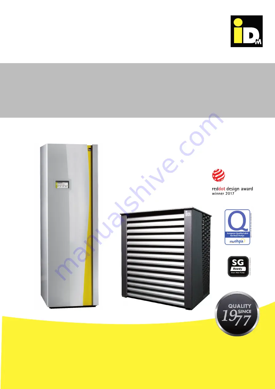
iDM iPUMP A 2-7 Скачать руководство пользователя страница 1

i P U M P   A   2 - 7

i P U M P   A   3 - 1 1


    W I T H   N AV I G AT O R   2 . 0

iDM iPump A/T

THE 

ENERGY

FAMILY

TECHNICAL DOCUMENTATION

INSTALL ATION INSTRUCTIONS

HEAT PUMPS

 FROM AUSTRIA 

www.idm-energie.at

812548 Rev

.19 - 

T

ranslation of original instruction

AIR HEAT PUMP WITH 
INVERTER-TECHNOLOGY 

Содержание iPUMP A 2-7

Страница 1: ...TH NAVIGATOR 2 0 iDM iPump A T THE ENERGYFAMILY TECHNICAL DOCUMENTATION INSTALLATION INSTRUCTIONS HEAT PUMPS FROM AUSTRIA www idm energie at 812548 Rev 19 Translation of original instruction AIR HEAT PUMP WITH INVERTER TECHNOLOGY ...

Страница 2: ...r unit 10 3 6 Connections Outdoor unit 10 3 7 Technical data 11 3 8 Performance data iPump A 2 7 acc to EN 14511 13 3 9 Cooling data detailed iPump A 2 7 14 3 10 Filling quantity refrigerant 17 3 11 Maximum heigth difference 17 3 12 Linits of use 18 3 13 Performance data iPump A 3 11 acc to EN 14511 20 3 14 Cooling data detailed iPump A 3 11 21 3 15 Filling quantity refrigerant 24 3 16 Maximum hei...

Страница 3: ...e refrigerant pipes 43 8 ELECTRICAL ASSEMBLY 44 8 1 Electrical power supply 44 8 2 Electrical connection indoor unit 44 8 3 Electrical connection indoor unit 44 8 4 Electrical connection of the outdoor unit 45 8 5 Connection diagram of the electrical module 46 8 6 Connection of the central unit 47 9 COMMISSIONING 48 9 1 Notes for commissioning 48 9 2 Appliance and operation 48 9 3 Faults 48 10 MAG...

Страница 4: ...m must be shut off and secured against re activation In addition all safety instructions in the relevant do cumentation stickers on the heat pump itself and all other applicable safety regulations must be observed 1 General information 1 3 Storage Heat pump components may not be stored outdoors Heat pumps should not be stored in wet rooms or in potentially dust rooms 1 4 Installation room The inter...

Страница 5: ...rovided by the customer if required 1 9 Cleaning If necessary the internal and the outdoor unit of the iPump A can be cleaned with a damp cloth The use of cleaning agents is not recommended 1 10 Ser vicing and maintenance Regular maintenance control and servicing of all system components guarantee its safe and econo mical operation in the long term To achieve this we recommend a maintenance contra...

Страница 6: ... by humans the legislation defines limit values that must not be exceeded Sound propagation outdoor With increasing distance from a point noise source the sound power is distributed on an increasing area due to spherical spreading Therefore the sound pressure level is continuously decreasing with in creasing distance from the noise source to receiver location Doubling the distance leads to a reduc...

Страница 7: ...tion incorporation 3 or 6 dB A Impulsiveness 0 3 or 6 dB A Daytimes with increased sensitivity 6 dB A The rating level Lr shall be obtained by summing the calculated immission level and the applied correc tions of the specific periods Finally the determined rating level can be compared with legal limit values e g TA Lärm Standard Immission Values SIV relevant place of immission outside the buildin...

Страница 8: ...he circulation The lower the maximum flow temperature is set the higher is the efficiency of the heat pump The electrical lines and refrigerant con nection pipes between the indoor and out door units are not in the scope of delivery The parts are available as accessories and must be connected according to the technical specifications 3 1 Intended use For monovalent heating and cooling of single and m...

Страница 9: ...3 Dimensions indoor unit 9 10 2 1 3 4 5 6 7 8 Bottom view Front view 1 Heating supply 1 2 Heating return 1 3 Hot water connection 3 4 4 Cold water connection 3 4 5 Inlet cables of sensors 6 LAN Connection 7 Circulation connection 3 4 8 Cable inlet main current 9 Refrigerant pipe liquid line 12 mm 10 Refrigerant pipe hot gas line 16 mm 3 4 Connections indoor unit ...

Страница 10: ... 3 11 10 Description Montage Heizungsseitig Front view Side view left Inlet side Outlet side 3 5 Dimensions Outdoor unit Refrigerant pipe connections Ø10 mm and Ø12 mm resp Ø12 mm und Ø16 mm Condensation drain 1 Outlet side Inlet side 3 6 Connections Outdoor unit View from below ...

Страница 11: ...12102 outdoor unit dB A 49 53 Sound reduced operation outdoor unit reduced power dB A 46 49 The sound pressure level can be calculated with the iDM sound calculation tool Dimensions indoor unit Height Width Depth mm 1950 600 786 Tilted height mm 2150 2150 Weight kg 251 270 Minimum size of installation room2 with standard filling m 7 27 9 32 Dimensions outdoor unit Height Width Depth mm 1180 1110 7...

Страница 12: ...e 10 m4 Electrical data Electrical power supply compressor V Hz 1 230 50 1 230 3 400 Electrical power supply heating unit V Hz 3 400 50 3 400 50 Electrical power supply controller V Hz 1 230 50 1 230 50 Maximum operating current of compressor A 15 8 9 24 Maximum operating current of ventilator A 0 24 0 5 Maximum power consumption ventilator W 56 113 Performance factor cos phi 1 0 98 Maximum power ...

Страница 13: ...1 17 1 31 4 08 3 94 3 89 3 67 3 40 2 89 2 24 2 02 1 71 1 53 2 00 1 82 1 92 1 73 1 83 2 02 2 21 2 39 2 33 2 43 0 59 0 58 0 58 0 58 0 59 0 64 0 79 0 95 1 08 1 31 1 53 1 68 2 01 2 20 2 86 3 43 3 83 4 11 4 05 4 13 20 15 12 10 7 2 7 10 15 18 2 42 2 99 4 52 5 09 6 53 7 95 8 56 9 00 9 04 9 26 2 83 2 82 2 83 2 80 2 76 2 43 2 58 2 54 2 51 2 47 3 27 3 20 3 18 3 06 2 88 2 69 1 97 1 78 1 19 0 98 2 00 2 00 2 1...

Страница 14: ...PPMJOH DBQBDJUZ kW 1PXFS DPOTVNQUJPO kW EER Ϯ ϲϮ ϯ ϭϳ ϯ ϳϱ 4 36 5 08 5 67 4 59 4 95 5 63 6 11 6 51 6 85 1 06 1 03 0 86 0 76 0 64 0 52 PPMJOH DBQBDJUZ kW 1PXFS DPOTVNQUJPO kW EER 4 33 4 80 6 53 8 09 10 16 13 25 2 59 2 90 3 08 3 23 3 31 3 38 0 51 0 43 0 36 0 29 0 25 0 20 PPMJOH DBQBDJUZ kW 1PXFS DPOTVNQUJPO kW EER 5 06 6 79 8 61 11 19 13 48 16 54 40 35 30 25 20 15 6 84 7 49 8 04 8 66 9 17 9 68 2 82 ...

Страница 15: ...gsseitig Heating output iPump A 2 7 at flow temperature 35 C Heating output iPump A 2 7 at flow temperature 45 C Ϭ Ϯ ϰ ϲ ϴ ϭϬ ϭϮ ͲϮϬ Ͳϭϱ ͲϭϬ Ͳϱ Ϭ ϱ ϭϬ ϭϱ ϮϬ HeDW FDSDFLW kW 2XWGRRU temperaturH C D y EKD D E Ϭ Ϯ ϰ ϲ ϴ ϭϬ ϭϮ ͲϮϬ Ͳϭϱ ͲϭϬ Ͳϱ Ϭ ϱ ϭϬ ϭϱ ϮϬ HeDW FDSDFLW kW 2XWGRRU temperaturH C DĂdž EKD D E ...

Страница 16: ...eizungsseitig Heating output iPump A 2 7 at flow temperature 55 C Heating output iPump A 2 7 at nominal speed Ϭ ϭ Ϯ ϯ ϰ ϱ ϲ ϳ ϴ ϵ ϭϬ ͲϮϬ Ͳϭϱ ͲϭϬ Ͳϱ Ϭ ϱ ϭϬ ϭϱ ϮϬ HeDW FDSDFLW kW 2XWGRRU temperaturH C DĂdž EKD D E ϭ Ϯ ϯ ϰ ϱ ͲϮϬ Ͳϭϱ ͲϭϬ Ͳϱ Ϭ ϱ ϭϬ ϭϱ ϮϬ Ϯϱ HeDW FDSDFLW kW 2XWGRRU temperaturH C tϯϱ tϰϱ tϱϱ tϱϬ tϲϬ ...

Страница 17: ...stalled before the inclination In case of a higher height difference the installation must be done after 5 m The oil elevation arc must be installed by a certificated service technician Whether the indoor unit or the outdoor unit is higher does not matter The maximum height difference between indoor unit and outdoor unit is 10 m 0 0 1 0 2 0 3 0 4 0 5 0 6 0 7 0 8 0 2 4 6 8 10 12 14 16 18 20 ZĞͲĨŝůů Ƌ...

Страница 18: ...mitation with automatic reset via the NAVIGATOR control Starting current limiter via inverter technology and performance adjustment 20 10 0 5 10 20 30 35 40 30 40 50 60 20 C C R410A 62 42 Outdoor temperature Flow temperature iPump A 2 7 Heating Heating The maximum heat pump flow temperature is the highest temperature that the heat pump can produce depending on the heat source temperature and is the...

Страница 19: ... the heat source temperature and is then switched off at this value Due to the hydrau lic spread across the heat pump the control related switching hysteresis and the humidity dependent dew point it is not possible to reach this temperature in the cooling circuit The lowest possible management temperature depends on the hydraulic design the configuration and the actual dew point on site and is at l...

Страница 20: ...95 3 36 2 64 2 41 2 11 1 99 Heizleistung 0 8 2 0 8 2 0 8 2 0 8 2 0 8 2 0 8 2 0 8 2 1 2 3 0 8 3 2 4 4 W k Power intake 4 2 2 3 9 1 6 5 1 9 3 1 8 0 1 6 7 0 8 6 0 1 7 0 8 7 0 3 8 0 W k 5 2 1 5 4 1 0 8 1 1 0 2 0 6 2 0 7 3 1 1 4 0 5 4 5 8 4 0 3 5 P O C 20 15 12 10 7 2 7 10 15 18 Heat output 1 0 3 1 1 3 3 7 3 2 1 4 1 3 5 5 2 6 2 8 6 1 1 7 8 5 7 1 2 8 W k Power intake 6 6 1 5 6 1 1 7 1 0 7 1 5 7 1 7 7 1 ...

Страница 21: ...k 2 7 4 5 2 4 8 7 3 0 3 3 3 8 2 5 3 2 R E E Cooling capacity 3 9 6 5 5 6 7 1 6 8 7 5 0 4 5 2 0 5 W k Power intake 9 3 1 5 4 1 2 5 1 1 6 1 4 7 1 1 9 1 W k 0 0 5 3 5 4 6 0 4 8 5 3 1 1 3 3 6 2 R E E Cooling capacity 7 8 2 2 9 2 5 9 2 5 9 2 3 9 2 8 8 2 W k Power intake 4 6 0 2 7 0 1 8 0 2 9 0 6 0 1 4 2 1 W k 0 5 4 7 0 4 4 6 3 0 2 3 6 7 2 2 3 2 R E E ůŽǁ ƚĞŵƉĞƌĂƚƵƌĞ W7Σ MAX NOMINAL KƵƚĚŽŽƌ temperature ...

Страница 22: ...eizungsseitig Heat output iPump A 3 11 at flow temperature 35 C Heat output iPump A 3 11 at flow temperature 45 C 0 2 4 6 8 10 12 14 20 15 10 5 0 5 10 15 20 Heat output kW Air inlet temperature C MAX NOMINAL MIN 0 2 4 6 8 10 12 14 20 15 10 5 0 5 10 15 20 Heat output kW Air inlet temperature C MAX NOMINAL MIN ...

Страница 23: ...sseitig Heat output iPump A 3 11 at flow temperature 55 C Heat output iPump A 3 11 at nominal speed 0 2 4 6 8 10 12 14 20 15 10 5 0 5 10 15 20 Heat output kW Air inlet temperature C MAX NOMINAL MIN 2 3 4 5 6 7 8 9 10 20 15 10 5 0 5 10 15 20 25 Heat output kW Air inlet temperature C W35 W45 W50 W55 W62 ...

Страница 24: ... ƋƵĂŶƚŝƚLJ ŝWƵŵƉ ϯͲϭϭ WŝƉĞ ůĞŶŐƚŚ ŝŶ ŽŶĞ ĚŝƌĞĐƚŝŽŶ ŵ ZĞĨƌŝŐĞƌĂŶƚ ƋƵĂŶƚŝƚLJ ŬŐ ZĞͲĨŝůů ƋƵĂŶƚŝƚLJ ŬŐ Ϭ ϰ ϭϬ Ϭ ϲ ϰ ϭϬ Ϭ ϭϬ ϰ ϰϬ Ϭ ϯϬ ϭϱ ϰ ϴϬ Ϭ ϳϬ ϮϬ ϱ ϮϬ ϭ ϭϬ 3 16 Maximum heigth difference If the height difference between the indoor unit and outdoor unit is lower than 5 m no oil elevation arc must be installed before the inclination In case of a higher height difference the installation must be done afte...

Страница 25: ...atic reset via the Navigator control Starting current limiter via inverter technology and performance adjustment Heating 20 10 0 5 10 20 30 35 40 30 40 50 60 20 C C R410A 62 42 Heating supply temperature Ambient air temperature iPump A 3 11 Heating The maximum heat pump flow temperature is the highest temperature that the heat pump can produce depending on the heat source temperature and is then sw...

Страница 26: ...m heat pump flow temperature is the lowest temperature that the heat pump can produce depending on the heat source temperature and is then switched off at this value Due to the hydrau lic spread across the heat pump the control related switching hysteresis and the humidity dependent dew point it is not possible to reach this temperature in the cooling circuit The lowest possible management temperat...

Страница 27: ...Transport of the Indoor unit via stairways The heat pump can be lifted down the stairways step by step with a sack barrow A sufficient number of persons for securing the device during the transport shall be present If the heat pump must be transported without the wooden pallet and the protective wooden crate it is important that there will be no damage on the housing Transport of the outdoor unit Th...

Страница 28: ... that the front panel is only handled on the right and left side as shown in the photo It is not allowed to lift the front panel at the design edge of the panel otherwise the Front panel could be damaged After the front panel is removed the fixing screws of the side parts will be loosed The fixing screws are located on the front as shown in the photo on the left side The side parts and the rear pa...

Страница 29: ... screws This screws must be loosened After this the rear panel can be removed from the base frame At the front of the iPump the electrical pan and the main board are located above the refrigerating equip ment The electrical pan can be hinge down when loosing the fixing screws The electrical pan is secured by a safety rope against unintentional hinge down Anyway ensure that the electrical pan does ...

Страница 30: ...ed down After this the return line can be dis connected from the hot water tank The hose clamp is under the Armaflex insulation To open the hose clamp the insulation must be pulled down The bolting of the common supply pipe for heating and domestic hot water preparation can be loosened with a pipe wrench The bolting is located in the front of the iPump on the right side under the electrical pan Un...

Страница 31: ... disconnected The sensors B41 and B48 are mounted in the immer sion sleeve with a clip The sensor B33 is located under the Armaflex insula tion The sensor must be pulled out carrfully Also the connection cable to the flow rate transmitter B2 and the LAN connection for myiDM must be dis connected The plug for the switching valve must be disconnec ted B48 B41 LAN connection B2 B33 LAN connection Hot...

Страница 32: ... screws the iPump can be split Thereby it is possible to transport the hot water tank and the refrigeration equipment separately On the front side of the iPump base frame there are six and on the back side are four connecting screws To loos the screws on the front side the electric pan must be lifted by a second person Once all connecting screws are loosened and remo ved the hot water tank can be ...

Страница 33: ... unit of the iPump is not connected on delivery The connecting cable to the control unit is fixed inside the front part by a cable strap The black cable is connected to the USB port The connection cables are inside of a flexible hose The flexible hose will be fixed by a clamp for strain relief in the electric pan Before the cable will be pluged the flexible hose must be fixed in the strain relief ...

Страница 34: ...observed at the front and depending of the connection of the refrigerant pipes on the right or left side of the heat pump see the opposite diagram The connection for the circulation line is located on the front side of the storage tank behind the electrical tub This must be folded downwards for installation The connections for the refrigerant lines are either on the right or on left side The conne...

Страница 35: ... must be recessed around the heat pump to ensure low noise levels when the heat pump is operating see adjacent illustration In the shipment of iPump A heat pumps are two pcs of sound insulation mats The mats must be placed under the heat pump The internal unit of the iPump must be lowered tight to the sound insulation mats after the sound insulation mats have been placed underneath This is done by...

Страница 36: ...ght side of the heat pump After the system has been disconnected from the power supply the front part must be removed first and the electric can be folded downwards The switching valve with the motor is located in the foamed buffer seen from the front on the upper right hand side pic 1 Now reach behind the motor with your right hand There you reach the locking ring which holds the motor at the swit...

Страница 37: ...separately The connecting lines must be insulated in order to minimise losses through the earth Installation site preparations Take the following points into account when installing the outdoor device The maximum pipe length between the external and the indoor unit may not be more than 20 meter in one direction For difference height between indoor and outdoor unit see page 17 The installation site ...

Страница 38: ...g capacity of the wall bracket must be given The unit must be fixed with four screws M10 Air heat pumps are producing condensation water during operation This could be 6 liters per defrost cycle within 2 minutes The condensate run off must be frost proof The outdoor unit already includes a heated conden sate run off tray to avoid freeze The condensate run off also has to be heated with the already mo...

Страница 39: ...e glued in and the glue is cured the hexagon nuts and the washers will be mounted on the threaded bars After this the outdoor unit will be placed and brought into the correct position At the end the outdoor unit will be countered and secured with the washers and the hexagon nuts 6 8 Earthing of the heat pump system If the protective conductor is correctly connected the control panel and the housin...

Страница 40: ...off adapter The heating band 2 m will be placed in the drain hose The condensation bin and the run off have to be checked for soiling regularly min 600 mm min 500 mm min 500 mm Exhaust side Suction side barrier barrier barrier The minimum distances must be maintained due to perform maintenance 6 11 Minimum distances When installing the outdoor unit there must be spe cial attention to avoid air flow ...

Страница 41: ...unit and outdoor unit are not included in the delivery They are available as an accessory and can be ordered by the iDM dealer 7 2 Connection of the outdoor unit on refri gerant side The refrigerant pipes are factory fitted with protective caps Before soldering the refrigerant connection lines check that the two shut off valves are fully closed For connecting the refrigerant lines the pro tective c...

Страница 42: ...unit To connect the refrigerant pipes the protecting caps must be cut The refrigerant pipes must be cut with a pipe cutter to the required length The burrs must be removed with a deburring tool Soldering must be carried out under inert gas Nitro gen N2 Do not open or cutt of the refrigerant pipes until they are properly soldered The connection of the refrigerant pipes and the refrigerant may only ...

Страница 43: ... under plaster 7 6 Important information about the instal lation of the refrigerant pipes The refrigerant pipe connections and the refrigerant itself may only be handled by trained experts autho rised by iDM Energiesysteme GmbH The refrigerant flow through the indoor unit can lead to flow noises The refrigerant pipes must be uncoupled from the building and must not be laid under plaster Ensure tha...

Страница 44: ...ntal temperature UV resistance electromagnetic compatibility Before commissioning the system check all terminals and tighten if necessary The mains voltage at the terminals of the heat pump must be 230 V or 400 V 10 depending on the type 8 2 Electrical connection indoor unit For iPump A heat pumps separate cable entries for the main power supply and for the sensors have been designed to avoid prob...

Страница 45: ... Electrical connection box for the ventilator Connecting line from the indoor unit to the out door unit The power supply of control for the outdoor unit will be energised via the indoor unit In addition a data cable must be routed Control current ÖLFLEX CLASSIC 100 BK 5G1 5 Bus connection Li2YCYv TP 2x2x0 5 mm If the iPump should be connected to my iDM Network the network cable must be provided on...

Страница 46: ...N LAN X33 RS232 X36 100 102 103 104 106 107 108 109 110 111 112 113 114 115 116 117 118 119 120 121 122 123 1 N 10 N N 11 N 12 181 180 F8 F4 F10 F9 F3 F7 F6 F1 F2 F5 X42 X2 X4 ON 2 1 ON 2 1 H4 H5 H6 H7 H3 H2 H1 230V 50Hz CAN Bus CAN Bus RS485 Bus LED LAN X33 RS232 Bus S1 S2 Triac Mains Triac outputs T 800mA 1500A Digital inputs 230V Clamp 100 123 T 3 15A 1500A Triac outputs Clamp 10 T 3 15A 1500A ...

Страница 47: ...nd corrosion free Sensor lines should be run separately form mains cables see EMC issue It is recommended to use shielded cable Sensor equipment The following sensors are included as standard or are already fitted and are necessary in all cases Heating supply sensor B33 Heating return sensor B34 Heat source outlet sensor B36 Heat source inlet sensor B43 Domestic hot water sensor top area B41 Domes...

Страница 48: ...quirements The refrigerant connection pipes between the in door and outdoor unit must be installed The heat pump may only be switched on when the refrigerant side and the heating side is filled and all electrical connections are checked At air source heat pumps a heating buffer tempe rature of min 20 C must be guaranteed in order to ensure the required temperature for the reference defrosting 9 2 A...

Страница 49: ...closed After about 30 sec the measured value is set Interpretation of the measurement results The measured value depends on the quality of the enamel the buffer size the electrical conductivity of the water the installation of brass immersion sleeves or non enameled components For the buffer of the iPump A the measured protective currents are in the range of 1 mA As a critical lower limit a protecti...

Страница 50: ...ed In order to protect the underlying electric from any escaping residual water it is best to cover it with a foil The black connection line between the anode and the buffer must be terminated Then the anode can be unscrewed by a suitable pipe wrench The used magnesium protective anode can now be pulled out and replaced by a new one The new anode will be screwed firmly and the black connection cabl...

Страница 51: ...e 90 must be connect to the anode The blade receptacle straight must be connected to the buffer On the cable itself there is an indication that it is the ground connection The electrical connection of the external current anode is carried out according to the enclosed wiring diagram The distribution socket must be connected to the wiring diagram of the heat pump the socket can be mount in the elect...

Страница 52: ...alling an IDM heat pump in the heating system This suggestion replaces no professional planning of an executing companie On part of IDM Energiesysteme can no warrenty be taken concerning the function of the whole system iPump A Direct circuit for heating indoor unit outdoor unit HW HC B RE B OS Circulation CW Refrigerant pipes When using direct heating circles and zone valves at least 25 of the zo...

Страница 53: ...rgiesysteme can no warrenty be taken concerning the function of the whole system iPump A Direct and mixer circuit for heating indoor unit outdoor unit HW HC B RE B OS Circulation CW Refrigerant pipes RE A HC A FS When zone valves and direct circuits are used at least 25 of the onen must remain permanently open Exception With the NAVIGATOR Pro all zones can be equipped with actuators The AVIGATOR c...

Страница 54: ...scale forming For filling heating systems very clear guidelines apply relating to the heating water quality Specifically European standard EN 12 828 ÖNORM H 5195 and in particular VDI Guideline no 2035 must be observed and represent the current state of art You must also check the pH value of the heating water It should be between 8 2 and 9 5 In order to prevent damage through corrosion silt up or...

Страница 55: ...FRPSUHVVRUV HQHUDO WHFKQLFDO DWD RX FDQ ILQG RQ WKH QDPHSODWH FKDQJH WR WKH GHYLFH V QRW DXWKRUL HG E XV ZLOO UHQGHU WKLV GHFODUDWLRQ LQYDOLG 8 LUHFWLYHV RZ 9ROWDJH LUHFWLYH 8 0 LUHFWLYH 8 FRGHVLJQ LUHFWLYH 8 3UHVVXUH TXLSPHQW LUHFWLYH 8 52 6 LUHFWLYH 8 8 5HJXODWLRQV 5HJXODWLRQ 8 QU RQ PSOHPHQWDWLRQ RI LUHFWLYH 8 5HJXODWLRQ RI IOXRULQDWHG JUHHQKRXVH JDVHV 8 UHJXODWLRQ QU HWDLOV 8 3 8 OXLG JURXS DW...

Страница 56: ...ing energy efficiency ɻs cold 178 129 average 202 150 warm 281 192 seasonal Coefficient of Performance SCOP Ͳ kalt 4 52 3 29 mittel 5 13 3 75 warm 7 09 4 87 rated heat output Prated kW cold 6 5 average 5 4 warm 6 7 annual energy consumption QHE kWh cold 3136 3407 average 2166 2368 warm 1304 1900 sound power level LWA dB A indoor 42 42 outdoor 46 46 specific precautions that shall be taken when the...

Страница 57: ...50 120 average 176 135 warm 217 175 seasonal Coefficient of Performance SCOP Ͳ kalt 3 82 3 07 mittel 4 47 3 44 warm 5 54 4 45 rated heat output Prated kW cold 10 9 average 9 8 warm 9 10 annual energy consumption QHE kWh cold 6 388 7 104 average 4 115 4 887 warm 2 329 3 108 sound power level LWA dB A indoor 45 45 outdoor 50 50 specific precautions that shall be taken when the space heater is assemb...

Страница 58: ...perature T biv COP d 2 04 2 11 2 31 T j Operation limit temperature TOL P dh 3 4 4 5 6 5 kW T j Operation limit temperature TOL COP d 1 86 2 11 2 31 Bivalenz temperature Tbiv T biv 15 0 10 0 2 0 C Operation limit temperature TOL 18 0 10 0 2 0 C Cycling interval capacity for heating P cych kW Cycling interval capacity for heating COP cyc Degradation co efficient C dh 0 9 0 9 0 9 Heating water opera...

Страница 59: ...rature 20 C indoor temperature 20 C T j Operation limit temperature TOL P dh 6 9 8 5 9 9 kW T j Operation limit temperature TOL COP d 1 82 2 02 2 36 Bivalenz temperature Tbiv T biv 15 0 10 0 2 0 C Operation limit temperature TOL 18 0 10 0 2 0 C Cycling interval capacity for heating P cych kW Cycling interval capacity for heating COP cyc Degradation co efficient C dh 0 9 0 9 0 9 Heating water opera...

Страница 60: ... SITE SERVICE Our service technicians are happy to help on site Contact details for your regional customer service centre can be found on our website iDM Academy PRACTICAL KNOWLEDGE FOR SALES AND TECHNOLOGY The comprehensive range of seminars for specialists at the IDM POWER FAMILY is available to you any time on our website We look forward to receiving your registration YOUR iDM PARTNER ...

Отзывы: