


67
HS5E-K Interlock Switches with Key
Instructions
Actuator Angle Adjustment (vertical/horizontal)
•
Using the angle adjustment screw, the actuator angle can
be adjusted (refer to the dimensional drawing on page 62) .
Adjustable angle: 0 to 20°
•
The larger the adjusted angle of the actuator, the smaller
the applicable radius of the door opening . After installing
the actuator, open the door . Then adjust the actuator so
that its edge can be inserted properly into the actuator
entry slot of the interlock switch .
•
After adjusting the actuator angle, apply Loctite to the
adjustment screw so that the screw will not move .
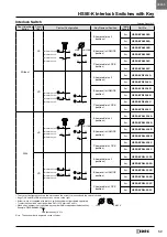
When using the HS9Z-A53 Angle Adjustable (vertical)
Actuator
•
When the door hinge is on the extension line of the inter-
lock switch surface: 50 mm
•
When the door hinge is on the extension line of the actua-
tor mounting surface: 80 mm
(36.2)
(38)
Inter
loc
k Switch
Mounting Hole
Inter
loc
k Switch
Mounting Hole
Door
Hinge
Door
Hinge
Minimum Radius
Minimum Radius
50 mm
80 mm
(68)
(56.5)
When using the HS9Z-A55 Angle Adjustable (vertical/
horizontal) Actuator
•
When the door hinge is on the extension line of the inter-
lock switch surface: 50 mm
•
When the door hinge is on the extension line of the actua-
tor mounting surface: 70 mm
When the door hinge is on the extension line of the interlock switch surface:
When the door hinge is on the extension line of the actuator mounting
surface
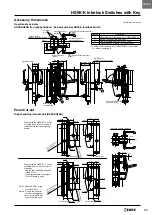
Mounting Examples
•
Mount the interlocks switch to a fixed machine or guard,
and mount the actuator on the hinged door . Do not mount
both interlock switch and actuator on the hinged doors,
otherwise malfunction will occur .
Actuator
HS9Z-A51
Door
Interlock Switch
HS5E-K
Door Stop
Application of Sliding Doors
Latch
Application of Hinged Doors
HS5E-K Interlock Switch
Install the interlock switch on the immovable part of the door.
Install the actuator on the movable part of the door.
HS9Z-A52 Actuator
HS9Z-SH5 Sliding Actuator
Door
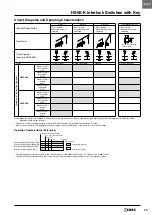
Installing the Head
Do not use plastic and metallic heads of HS5D/HS5B
interlock switches on the HS5E-K . Be sure to use HS5E
metallic heads . The metal heads of the HS5E, HS5D, and
HS5B look similar . When using these interlock switches
adjacently, ensure that the heads are not interchanged .
Color: Black
Plastic
Color: red,
black or gray
HS5E
HS5D/HS5B
Metallic Head
Metallic Head
Plastic Head
Metal
Color: Silver
Color: Gray
or red
∗
The metal head can be distinguished easily by the color of the
plastic .
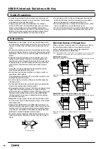
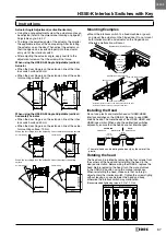
Rotating the head
The head can be rotated by removing the four screws from
the corners of the head and reinstalling the head in the
desired orientation . Before wiring the HS5E-K, replace the
head . Before replacing the head, turn the manual unlock
to the UNLOCK position using the manual unlock key .
When reinstalling the head, make sure that no foreign
object enters the interlock switch . Tighten the screws tightly,
without leaving a space between the head and body,
otherwise the interlock switch may malfunction .
(Recommended tightening torque: 0 .9 to 1 .1 N·m)
Head can be rotated
Factory Setting
LOCK
UNLOCK
LOCK
UNLOCK
LOCK
UNLOCK
LOCK
UNLOCK
(58)
(38)
Interlock Switch Mounting Hole
Interlock Switch Mounting Hole
(55.5)
(36.2)
(55.5)
(36.2)
70 mm
Minimum Radius
50 mm
Minimum Radius
Minimum Radius
50 mm
Minimum Radius
70 mm
Horizontal Swing
Vertical Swing
Horizontal Swing
Vertical Swing
Door Hinge
Door Hinge
Door Hinge
Door
Hinge
(58)
(38)
Interlock Switch Mounting Hole
Interlock Switch Mounting Hole
(55.5)
(36.2)
(55.5)
(36.2)
70 mm
Minimum Radius
50 mm
Minimum Radius
Minimum Radius
50 mm
Minimum Radius
70 mm
Horizontal Swing
Vertical Swing
Horizontal Swing
Vertical Swing
Door Hinge
Door Hinge
Door Hinge
Door
Hinge
HS5E-K


