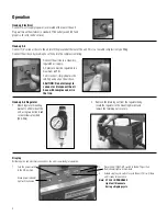
4. Observe the position of the trigger relative
to the indicating scale and loosen the
#8-32 socket head cap screw (use 5/32
hex wrench). Slide trigger to desired loca-
tion and retighten cap screw. Repeat this
procedure until all six triggers have been
set in their desired position.
Strip Length
Unit is equipped with six individual triggers. This allows
each wire port to be set-up to its own unique strip length.
1. Turn power switch to the OFF position. Leave air
supply connected.
2. Remove slug tray (Item 21)*.
3. Note position of wire port numbers 1 thru 6 from left to right with matching numbers
which correspond to the indicating scales on the contact plate (Item 19)*.
CONTACT PLATE (ITEM 19)*
TRIGGER ASSEMBLY (ITEM 16)*
8-32 CAP SCREW (ITEM 16)*
INDICATING SCALE
5. To check strip length, turn machine to its upright position and turn
power switch on. Strip several sample wires and verify proper strip
lengths. Repeat strip length adjustments as required.
CAUTION: Strip length range is 1/8” to 5/8”. Setting
strip length less than 1/8” may cause uncontrolled
cycling. Reset as required.
#2
#3
5
Operation (continued)
4. Insert the wire to be stripped into the wire guide hole until it engages the
trigger. Machine should cycle completely.
Note: Excessive force should not be required to
insert the wire into the proper wire guide.
CAUTION: The unit is designed to strip one wire per
cycle. DO NOT load multiple wires
simultaneously.
The unit is designed to accommodate as many as six blade and wire guide
configurations to speed production stripping jobs where more than one wire
type and size are to be stripped.
For increased operator comfort and efficiency the unit may also be adjusted to
operate at different angles from 00 (flat) to 450. Loosen knobs and spread the
Содержание Stripmaster 950
Страница 1: ...45 950 45 954 45 950 1 Stripmaster Model 950 Model 954 Wire Stripper...
Страница 14: ...Notes...
Страница 15: ...Notes...


