background image


1  

2  

3  

4  

5  


LABEL FORMAT

Single Line

Single line Plus

Double Line Plus

4 Character max each 

port

Top line 30 character 

max. 4 character max. 

each port

5 character max. each 

line each port

Wire Information


AWG 

Insulation 

Mil Spec 

Stripping Comments

1
2
3
4
5
6  

Comments  

Ordering Blades and Wire Guides

Due to varying manufacturing techniques, standard wire gauge sizes have begun to indicate “nominal” wire sizes and no longer indicate conductor 
diameters accurately. Therefore, in order to maintain accurate precision wire stripping, IDEAL requests that exact mil spec. information for the types of 
wire and insulation you will be stripping be provided to IDEAL when ordering blades and wire guides.
IDEAL also requests wire samples when ordering. If an IDEAL Custom Stripmaster™ Wire Stripper® hand tool is currently being used to strip the par-
ticular wire please specify the blade number being used with each wire type and size.
Due to varying outside diameter dimensions on every wire, IDEAL recommends ordering multiple wire guide bushings to match a given wire. 
Depending upon wire tolerances, it may be necessary to order a wire guide one size larger and one size smaller than supplied with the machine. Guides 
are easily interchanged to match varied wire size
When ordering, please specify the preferred face plate location and number designation for each blade/guide set.
For larger wire sizes (e.g. 10 AWG, 12 AWG, 14 AWG) blade location is preferred in the center ports of the machine.

Specification Chart Instructions

List the wire size,  insulation type and mil. spec. per each wire size and type for which you are ordering stripping blades and wire guides under the 
location/s (1 thru 6) you prefer.
Indicate numerical wire gauge legends (10 thru 30) or any identification you wish to appear above each corresponding air guide/blade configuration.
(Choose and complete the desired label format below.  1, 2 or 3)
Note:  For better stripping results, locate 10, 12, 14 gauge wires nearest to center ports.

12

Содержание Stripmaster 950

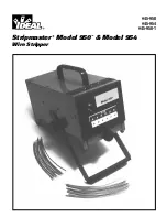
Страница 1: ...45 950 45 954 45 950 1 Stripmaster Model 950 Model 954 Wire Stripper...

Страница 2: ...y 4 Strip Length 5 Service Replacement Adjustment 6 Replacement Guide 7 Adjustments Clamp Stop 7 Adjustments Partial Strip 7 Circuit Board Adjustment 8 Stripmaster Model 950 950 1 Alignment Adjustment...

Страница 3: ...ries not recommended by IDEAL Technical Data Strip Lengths Minimum 125 inches 3mm Maximum 63 inches 16mm Strip Capacity Minimum 30 AWG 05mm2 Maximum 10 AWG 6 0mm2 Accuracy Meets Military specification...

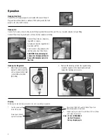
Страница 4: ...locate the regulator in the mounting bracket and replace the retaining nut securely Thermal Head Rotation Speed 4 Connect the air line to a clean dry regulated air supply Air pressure must be regulate...

Страница 5: ...ength turn machine to its upright position and turn power switch on Strip several sample wires and verify proper strip lengths Repeat strip length adjustments as required CAUTION Strip length range is...

Страница 6: ...ly adjusted tighten all blade holding screws 10 Reconnect air line to the face plate by inserting hose into the com pression fitting firmly 11 Reinstall front cover plate making sure clamp dowel pins...

Страница 7: ...e place use 7 64 hex wrench 3 Raise or lower set screws evenly use 1 16 hex wrench This will allow for an increase or decrease in the gripping force of the bush ings 4 Replace face plate NOTE One clam...

Страница 8: ...crewdriver Clockwise to increase delay and counterclockwise to reduce delay 3 Cycle the machine and continue to readjust as required 4 Replace top plate It may be desired to increase the time delay af...

Страница 9: ...raise or lower all six blades to their proper vertical position if needed Adjust both sides evenly 4 Install slug tray and top plate Adjustment Horizontal 1 Remove slug tray 2 Close blades using set u...

Страница 10: ...t screws use 3 32 hex wrench reposition the carriage left or right to obtain the proper alignment 4 Install slug tray Adjustments Permanent Faceplate Clamp Bar 1 With air connected to machines turn po...

Страница 11: ...cle n Empty the slug removal tray and make sure that all slugs have been removed from the unit n Disconnect the unit from the air and power supply and check to see that no insulation slugs are trapped...

Страница 12: ...sed with each wire type and size Due to varying outside diameter dimensions on every wire IDEAL recommends ordering multiple wire guide bushings to match a given wire Depending upon wire tolerances it...

Страница 13: ...2472 16 6 TRIGGER ASSEMBLY LB1526RP 17 5 SCREW 4 40 X 25 PH NYLON 358 033 ITEM REQ NAME PART NO 18 4 WASHER 4 NYLON 637 006 19 1 CONTACT PLATE LB1504 20 1 CUT YOKE K 6806 21 1 SLUG TRAY ASSEMBLY K 711...

Страница 14: ...Notes...

Страница 15: ...Notes...

Страница 16: ...rington Cheshire WA5 5TN England 44 1925 444 446 www idealind com Warranty limited solely to repair or replacement no warranty of merchantability fitness for a particular purpose or consequential dama...

Отзывы: