background image

6


Installation & Servicing

GENERAL

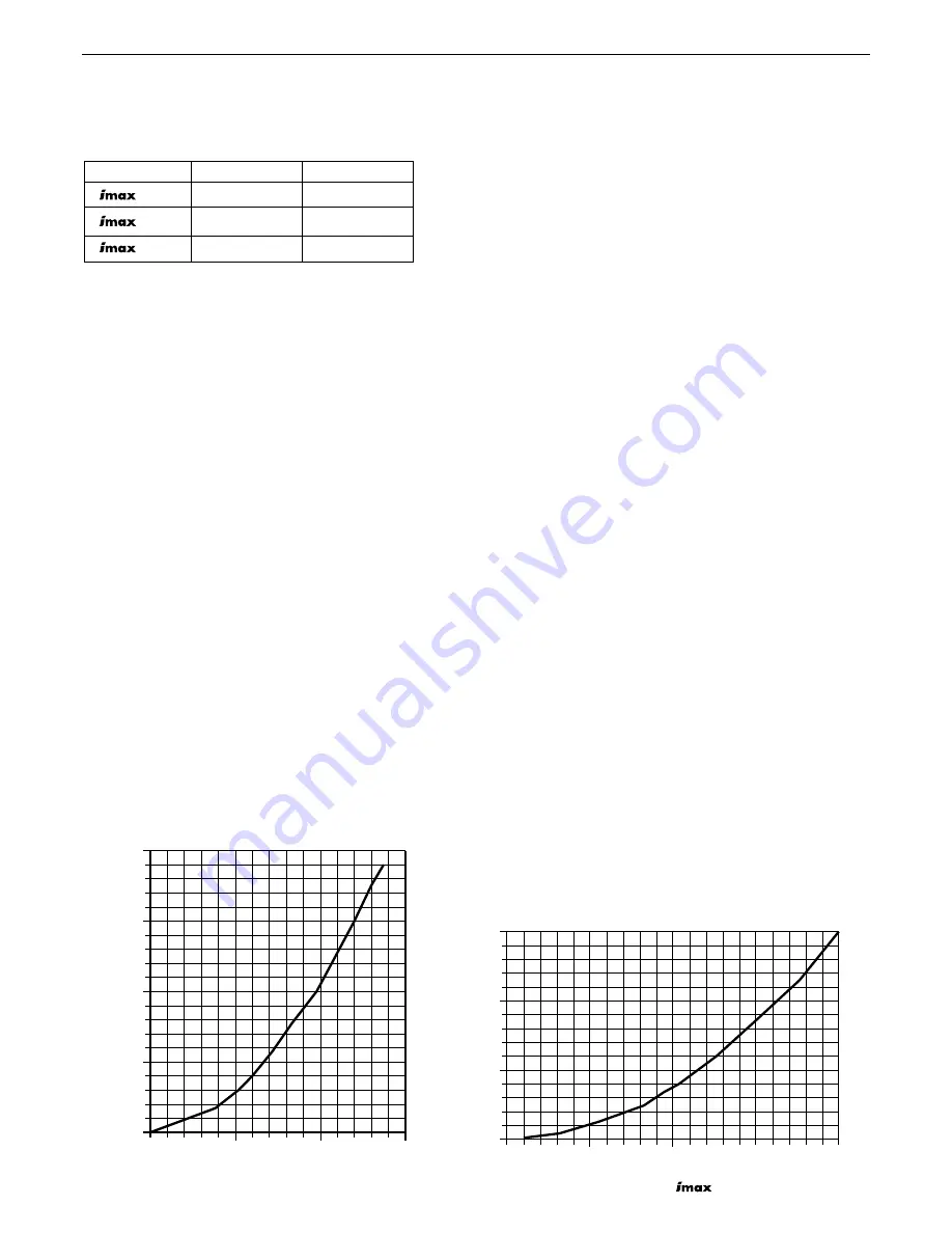
HYDRAULIC RESISTANCE W80

HYDRAULIC RESISTANCE W45 / W60

When sizing pumps, reference should be made to the graphs
below which show the boiler resistance against flow rates, to
achieve the required temperature differential.

Flow rates for common systems using either 11ºC or 20ºC
temperature differentials are given in the table below.

11ºC

20ºC

 W45

0.94 l/s

0.53 l/s

 W60

1.28 l/s

0.69 l/s

 W80

1.69 l/s

0.94 l/s

Note.

With the boiler firing at maximum rate, the temperature
differential should not be less than 10ºC.  High flow rates
required for lower temperature differentials could lead to
errosion of the heat exchanger water ways.

With the boiler firing at minimum rate, the temperature
differential should not be greater than 35ºC.  Lower flow rates
generating higher temperature differentials will lead to lock
out of the boiler.

The lower the return temperature to the boiler, the higher the
efficiency.

In installations where all radiators have been provided with
thermostatic radiator valves, it is essential that water circulation
through the boiler is guaranteed.  This can be best achieved by
means of a differential pressure valve, which is installed in a
bypass between the flow and return pipes.  The bypass should
be fitted at least 6m from the boiler, and should use a minimum
size of 28mm pipe.  The bypass should be capable of allowing a
minimum flow rate to achieve a temperature differential of no
greater than 35ºC at minimum rate.

WATER TREATMENT

These boilers incorporate an ALUMINIUM heat exchanger.

IMPORTANT. The application of any other treatment to this
product may render the guarantee of Caradon Ideal Limited
INVALID.

Caradon Ideal Limited recommend Water Treatment in
accordance with Guidance Notes on Water Treatment in Central
Heating Systems.

Caradon Ideal Limited recommend the use of Fernox Copal or
MB1, GE Betz Sentinel X100 or Salamander Corrosion Guard
inhibitors and associated water treatment products, which must
be used in accordance with the manufacturers' instructions.

For further information contact:

Fernox Manufacturing Co. Ltd., Cookson Electronics,
Forsyth Road, Sheerwater, Woking, Surrey, GU21 5RZ
Tel: +44 (0) 1799 521133
or
G E Betz Ltd, Sentinel Division, Foundry Lane, Widnes,
Cheshire, WA8 8UD
Tel: +44 (0) 151 424 5351
or
Salamander Engineering Ltd., Unit 24, Reddicap Trading Estate,
Sutton Coldfield, West Midlands, B75 7BU
Tel: +44 (0) 121 378 0952

Notes.

1. It is most important that the correct concentration of the water

treatment products is maintained in accordance with the
manufacturers' instructions.

2. If the boiler is installed in an existing system any unsuitable

additives MUST be removed by thorough cleansing.
BS7593:1992 details the steps necessary to clean a
domestic heating system.

3. In hard water areas, treatment to prevent limescale may be

necessary - however the use of artificially softened water is
NOT permitted.

4. Under no circumstances should the boiler be fired before the

system has been thoroughly flushed.

ELECTRICAL SUPPLY

Wiring external to the appliance MUST be in accordance with the
current I.E.E. (BS7671) Wiring Regulations and any local
regulations which apply.  For Ireland reference should be made
to the current ETCI rules for electrical installations

The point of connection to the mains should be readily
accessible and adjacent to the boiler.

CONDENSATE DRAIN

A condensate drain is provided on the boiler.  This drain must be
connected to a drainage point on site.  All pipework and fittings
in the condensate drainage system MUST be made of plastic -
no other materials may be used.

IMPORTANT. Any external runs must be insulated.

pressure drop (mbar)

0

200

150

100

50

0

0.5

1.0

1.5

waterflow litres/second

ima5391

pressure drop (mbar)

0

300

200

100

0

0.5

1.0

1.5

2.0

waterflow litres/second

ima5389

Содержание imax W45

Страница 1: ......

Страница 2: ...0 48 150 75 650 74 100 Gas Rate m3 h 4 76 1 84 6 35 2 45 8 46 3 27 ft3 h 168 65 224 86 299 115 Approx flue gas volume m3 h 72 68 98 93 131 123 ft3 h 2 540 2 400 3 460 3 280 4 620 4 340 CO2 Max Rate 8...

Страница 3: ...Kingdom Countries of destination PMS Maximum operating pressure of water C13 C33 A room sealed appliance designed for connection via ducts to a horizontal or vertical terminal which admits fresh air...

Страница 4: ...otland The Current I E E Wiring Regulations Where no specific instructions are given reference should be made to the relevant British Standard Code of Practice In IE the installation must be carried o...

Страница 5: ...of the installer to ensure in practice that products of combustion discharging from the terminal cannot re enter the building or any other adjacent building through ventilators windows doors other so...

Страница 6: ...Systems Caradon Ideal Limited recommend the use of Fernox Copal or MB1 GE Betz Sentinel X100 or Salamander Corrosion Guard inhibitors and associated water treatment products which must be used in acco...

Страница 7: ...urn Return Return Cond Drain Cond Drain Gas pipe Gas pipe Flue centre line 114 Flue centre line Flue centre line 80 125 Concentric Flue Connector W45 and W60 Minimum boiler top clearances for vertical...

Страница 8: ...elevant requirements of BS 6759 Pt 1 must be fitted in the flow pipe as close to the boiler as possible and with no intervening valve or restriction The valve should have the following features a A no...

Страница 9: ...plate 6 Internal flue tube 7 Air pressure switch 8 Fan 9 Mounting plate manifold 10 Gas Valve 11 Upper gas pipe 12 Lower gas pipe 12A Gas pipe 13 Sight glass complete 14 Ignition detection electrode...

Страница 10: ...After following the instructions on the box the boiler should be laying on its back with the straps removed Carefully read these installation instructions before proceeding Remove the outer packing s...

Страница 11: ...se damage or personal injury 1 Cut the flue hole ensuring that the hole is square to the wall Both wall faces immediately around the cut hole should be flat 2 Drill 4 holes with a 12mm 1 2 masonry dri...

Страница 12: ...h the attached bracket Boiler Size W45 W45P W60 W60P Minimum vent free 190 265 area cm2 If installed in a compartment then permanent air vents are required at high and low level These vents may commun...

Страница 13: ...e examples giving the maximum extensions which may be added The flue lengths achievable without any extensions are also provided For horizontal flues this is the distance from the flue outlet centre l...

Страница 14: ...aser Terminal Locking Collars x2 Finishing plates x2 Bracket RF 2499 Flue System Part No Max Flue Ext W45 W60 Vertical roof kit 80 125 158654 m 9 5 7 8 suitable for W45 W60 Pa 60 78 Vertical roof kit...

Страница 15: ...nal and the flue exhausted through either a vertical roof or horizontal wall terminal The maximum flue extension depends on the ratio of air to flue tube By fixing either the air or flue tube length y...

Страница 16: ...ollar Pitched Weather Collar 1m Extension concentric 1m Extension pair Twin pipe adapter 80 80 Increaser 80 100 152616 152618 n a n a 152611 152609 152400 n a n a n a 152617 152619 n a n a 152612 1526...

Страница 17: ...r or flue tube for the elbow required Concentric Flue Systems Pressure drop per component Pa m Pa m Pa m Terminals Vertical Roof flue kit 80 125mm 40 6 3 62 6 2 Vertical Roof flue kit 100 150mm 21 8 4...

Страница 18: ...w 2 x 11 2 x 1 1 Total flue resistance 104 10 4 The total maximum flue resistance for an W60 is 140Pa or 11m 80 125 Therefore this installation is acceptable Example 2 22 EXAMPLES OF CALCULATING FLUE...

Страница 19: ...llow correct connection of the ducts Care should be taken to support the inner duct when cutting the flue Note Horizontal flue runs must be angled down between 1 5 3 towards the boiler to allow the co...

Страница 20: ...car port roof From a vertical drain pipe or soil pipe From an internal or external corner or to a boundary alongside the terminal Above ground roof or balcony level From a surface or a boundary facing...

Страница 21: ...n the boiler capacity an ideal solution is to use multiple boiler arrangements The ideal way to control a multiple boiler installation is with our modulating sequencer See below a typical installation...

Страница 22: ...ion located at the bottom of the appliance Note This appliance is NOT suitable for use with a direct hot water cylinder Plastic plugs fitted into the open ends of the flow and return pipes must be rem...

Страница 23: ...e is used IMPORTANT The gas service cock contains a non metallic seal so must not be overheated when making capillary connections External wiring MUST be in accordance with the current I E E BS7671 Wi...

Страница 24: ...onnections for programmable room thermostat and modulating sequencer kits L SUPPLY N L PROG DHW STAT CH PUMP DHW PUMP OR VALVE CH STAT N L N L N ima5385 230VAC permanent mains supply Optional 230VAC s...

Страница 25: ...Burner switch KEY Blue Black Brown Red Yellow White g or v pk g y Grey Orange Violet Pink Green Yellow L DISPLAY BOARD b bk g y g or or or RY1 w v or y w r r r r b p bk w bk b g v RY2 1 2 3 4 5 6 7 8...

Страница 26: ...with the error code shown Refer to page 50 for error codes The boiler will enter error mode under certain fault conditions The unit will be inoperative until the fault is rectified The reset button i...

Страница 27: ...Parameter mode is entered from standby mode by pressing the mode button once S t b y P A R A Press the step button until the desired parameter is displayed Press the or buttons to change the values Th...

Страница 28: ...de 37 STANDARD CONTROLS ACCESS CONT D i N F O P A R A Press Display I N F O Actual Flow Temperature T1 C Press Display Description Actual Return Temperature T2 C 1 2 1 2 2 1 3 3 7 OUTSIDE Temperature...

Страница 29: ...th them 9 Code Mode By entering the service code the following additional features are accessible Parameters 5 to 42 Communication Mode Fan Speed Mode Error Mode Code Mode is entered from standby mode...

Страница 30: ...ence temperature compensation 15 25 20 2 0 Lowest outside temperature C That can influence temperature compensation 20 10 5 0 2 Outside temperature correction C For boiler reading of outside temperatu...

Страница 31: ...00 P15 Maximum fan speed DHW hundreds W45 55 W60 55 W80 Do not Do not 59 W45P adjust adjust 50 W60P 49 W80P 57 0 0 16 P16 Maximum fan speed DHW units W45 00 W60 00 W80 Do not Do not 00 W45P adjust ad...

Страница 32: ...00 Note 01 RMCI off 0 0 CH type 00 x0 Room thermostat x1 Outside temperature x2 N A x3 N A x4 0 10V capacity using BMS 0 10V kit x5 0 10V temperature using BMS 0 10V kit x6 control 0x N A First digit...

Страница 33: ...tion 1x CH pump off during heat request DHW normal pump function 2x CH pump normal function DHW pump 5 sec on delay after heat request 3x CH pump off during heat request DHW pump 5 sec on delay after...

Страница 34: ...boiler control module and optional controls interface kit There is communication between all devices FLASHING FLASHING I N F O Actual Flow Temperature T1 C 1 2 1 FLASHING Actual Return Temperature T2...

Страница 35: ...1st digit flashes and shows the current step The last two digits show the error code Error code see Table on page 48 for full list E R R O 1 3 6 FLASHING Boiler step 2 0 0 Flow temperature T1 Return...

Страница 36: ...t System pump maximum load 1 amp connect via a relay for greater currents 49 MAINS VOLTAGE CH AND DHW CONTROLS WITH DHW PUMP OUTPUT Pump Pump Non return valve Non return valve Cylinder thermostat PUSH...

Страница 37: ...cations see Frames 38 39 and 40 Parameter 35 03 If a live output is required from terminal 12 for positioning of the valve to satisfy CH demand Parameter 35 23 If a live output is required from termin...

Страница 38: ...t digit indicating the boiler is operating at minimum rate 13 Press the reset button to return to normal operating mode Note It is possible to switch off the CH DHW systems if the mode and buttons are...

Страница 39: ...inium oxide build up within the heat exchanger assembly is quite usual with this type of condensing boiler Though removal and cleaning is recommended annually the heat exchanger sump and condensate tr...

Страница 40: ...burner sealing gasket can be re used providing it shows no sign of damage The eight nuts and washers should be fitted following a diagonal tightening sequence twice The nuts should be secured firmly...

Страница 41: ...urner im 2524 62 HEAT EXCHANGER INSPECTION CLEANING 1 Remove the jacket front panel Refer to Frame 57 2 Remove the fan burner and gas valve assembly Refer to Frame 58 or 60 3 Inspect the heat exchange...

Страница 42: ...washer 5 Remove the four nuts securing the fan to the burner hood and lift out of the boiler 6 Remove the 2 screws securing the venturi to the fan inlet 7 Replace the fan using the new gaskets and fib...

Страница 43: ...Limited should be used as these are factory preset and require no adjustment 11 Reference should now be made to Frame 52 to check the gas rate 12 Check the operation of the boiler Refer to Frame 55 i...

Страница 44: ...k for gas soundness 10 Only Venturi s supplied by Caradon Ideal Limited should be used as these are factory preset and require no adjustment 11 Reference should now be made to Frame 52 to check the ga...

Страница 45: ...er to Frame 57 7 Pull the HT lead off the electrode 8 Remove the 2 screws 9 Replace the electrode using the new gasket provided ensuring that the earth lead is recaptivated under the screw and washer...

Страница 46: ...ry from the self sealing fitting 3 Unscrew the two screws from the pressure gauge bracket and withdraw the unit from the boiler 4 Compress the retaining lugs and remove the gauge from the bracket 5 Re...

Страница 47: ...rst to remove the transformer Refer to Frame 76 3 Disconnect the electrical connections from the module 4 Remove the four module fixing screws 5 Fit the new module and reassemble in reverse order 6 Ch...

Страница 48: ...tion Action E 00 Flame error Check inlet gas pressure Check flue for blockage Check wiring to ignition detection electrode Check condition of ignition detection electrode E 02 No ignition after restar...

Страница 49: ...meter Replace thermister E 32 Return thermistor short circuit Check wiring Disconnect terminals from thermister confirm short circuit using meter Replace thermister E 33 DHW thermistor short circuit...

Страница 50: ...d system check charge pressure If open vent system check minimum head is 3m Check wiring to water pressure switch Check water pressure switch with meter replace if necessary b 30 Flow return temperatu...

Страница 51: ...e 1 172 665 15 Auto air vent 1 172 668 21 Thermistor flow return 1 172 671 22 Transformer 1 172 657 23 Control Module W45 1 172 651 Control Module W60 1 172 652 Control Module W80 1 172 653 Control Mo...

Страница 52: ...52 Installation Servicing SHORT LIST OF PARTS 81 SHORT LIST 28 25 27 ima5558 14 15 21 22 23 24 26 10 7 8 29 W80 W45 60 30 early model late model...

Страница 53: ...53 Installation Servicing NOTES...

Страница 54: ...54 Installation Servicing NOTES...

Страница 55: ...55 Installation Servicing NOTES...

Страница 56: ...ing improvement in the design and performance of its products The right is therefore reserved to vary specification without notice The Ideal Boilers Technical Training Centre offers a series of first...

Отзывы: