


I-7532M-FD ( 2-port CAN/CAN FD Bridge ) User Manual (version 1.0.0)
Page: 9
Copyright © 2020 ICP DAS Co., Ltd. All Rights Reserved. E-mail: [email protected]
2.2. Pin Assignment
The pin assignments of CAN port and power connector of I-7532M-FD is shown in
the following tables.
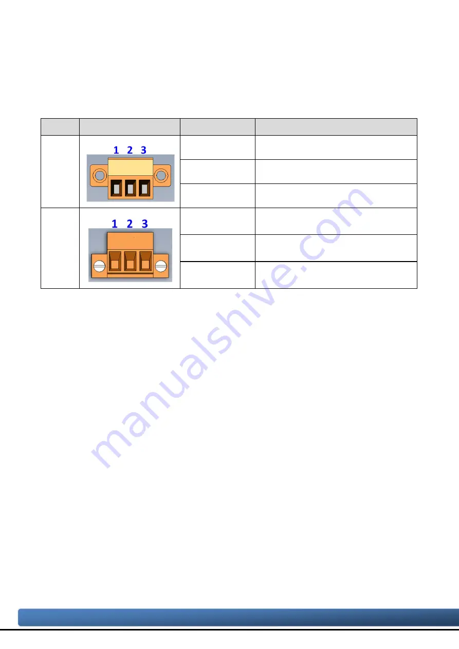
Table 2-2-1 Pin Assignment
Port
Schematic diagram
Pin
Description
CAN
1. CAN_GND CAN ground of CAN port
2. CAN_H
CAN_High bus line of CAN port.
3. CAN_L
CAN_Low bus line of CAN port.
Power
1. +Vs
Voltage Source Input.
+10V
DC
~ +30V
DC
.
2. GND
Power Ground.
3. F.G.
Frame Ground.
Sometimes, the CAN_GND voltage level of different CAN devices on a CAN bus
system are not equal. In this case, it could cause some problems and derogate the
system stability. There is one way to relieve this situation; users can connect the
CAN_GND of different CAN devices with each other to balance the voltage level of
CAN_GND.
Electronic circuits are always influenced by different levels of Electro-Static
Discharge (ESD), which become worse in a continental climate area. F.G. provides a
path for conducting the ESD to the earth ground. Therefore, connecting the F.G
correctly can enhance the capability of the ESD protection and improve the module’s
reliability.
Wiring of CAN_GND and F.G. is not necessary; users can modify the configuration
of wiring according to real applications.


