


23
triggered which causes the firmware to read the data from the ESC memory. The ESC
interrupts the firmware at fixed time interval to process the data received from the
master and write the status data to the ESC memory. Every time when the master
fails to sent process data within the DC cycle time the internal sync error counter is
being increase by three counts. This error counter is being decreased by one count
for every successful DC cycle. Once the error counter reached the maximum count
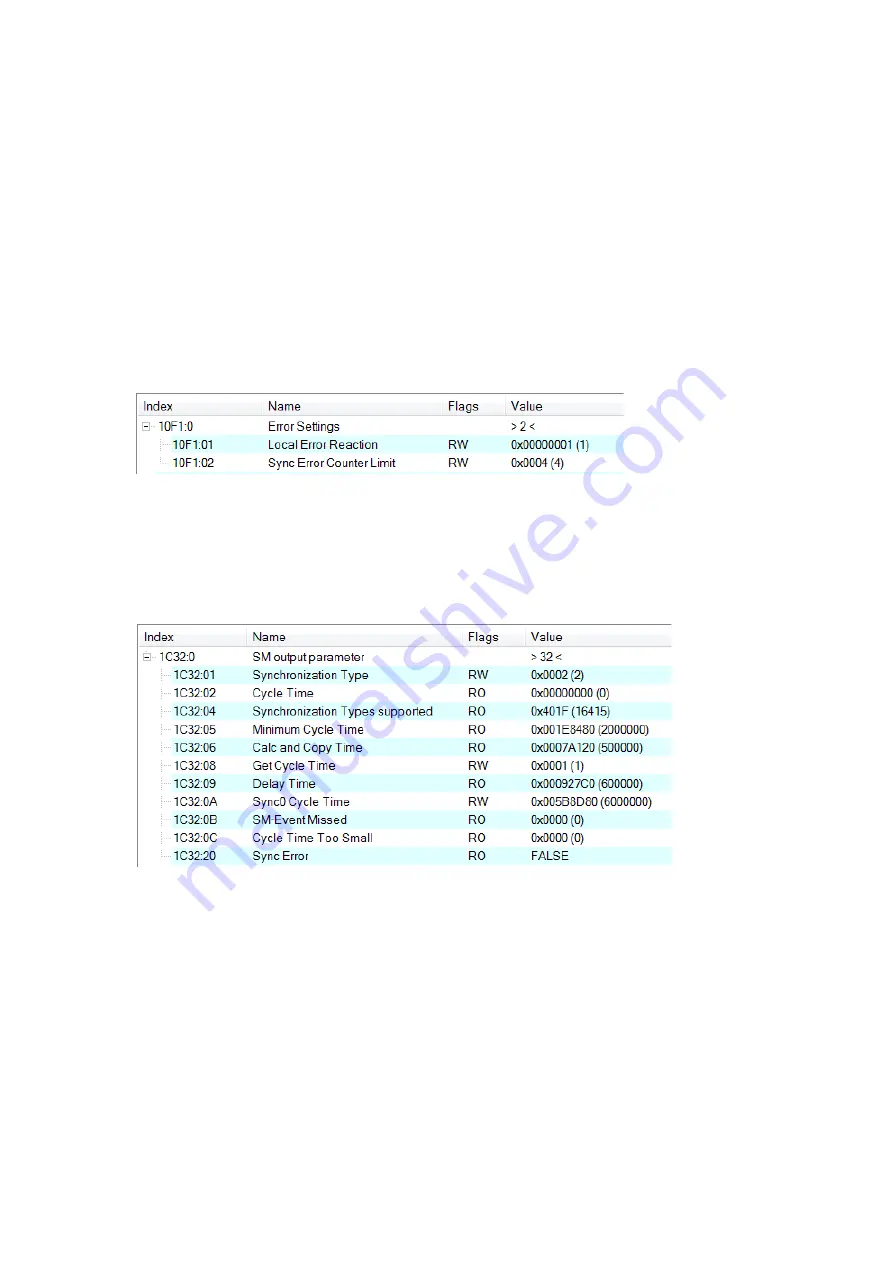
(default 4) a sync error will be generated and the slave goes into Safe OP mode (Sync
Error 0x1C32:20 true TRUE). The maximum count value can be set by changing the
default value of the "Sync Error Counter Limit" (0x10F1:02).
Figure 8: Sync error counter limit object
The setting of the sync manager for the output and input data is available at the
TwinCAT "CoE online" tab.
Figure 9: SyncManager 2 parameters
SyncManager parameter description (time unit: nanosecond):
Calc and Copy Time (0x1C32.6 / 0x1C33.6): Required time to copy the process
data from the ESC to the local memory and calculate the output value.
Delay Time (0x1C32.9 / 0x1C33.9): Delay from receiving the trigger to set the
output or latch the input.
Cycle Time (0x1C32.2 / 0x1C33.2): The current cycle time for the application.
When using DC synchronization the value is read from register 0x9A0:0x9A3.
0x1C32.5 / 0x1C33.5 (Min Cycle Time): Minimum cycle time for the application. It
Содержание ECAT-2094P
Страница 1: ...ECAT 2094P EtherCAT 4 Axis Pulse Output Module User Manual Version 1 0...
Страница 10: ...10 2 2 Alias Rotary Swtich The Alias range is 0x00 0xFF...
Страница 15: ...15 2 5 Stepper Motor Wiring...
Страница 17: ...17 Figure 2 Open collector wiring diagram...
Страница 24: ...24 is the total execution time of all slave application related operations...
Страница 71: ...71 Method35 37 The home detection position is the current position...


