background image

1

PANEL DESCRIPTION

1

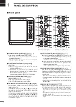
 Front panel

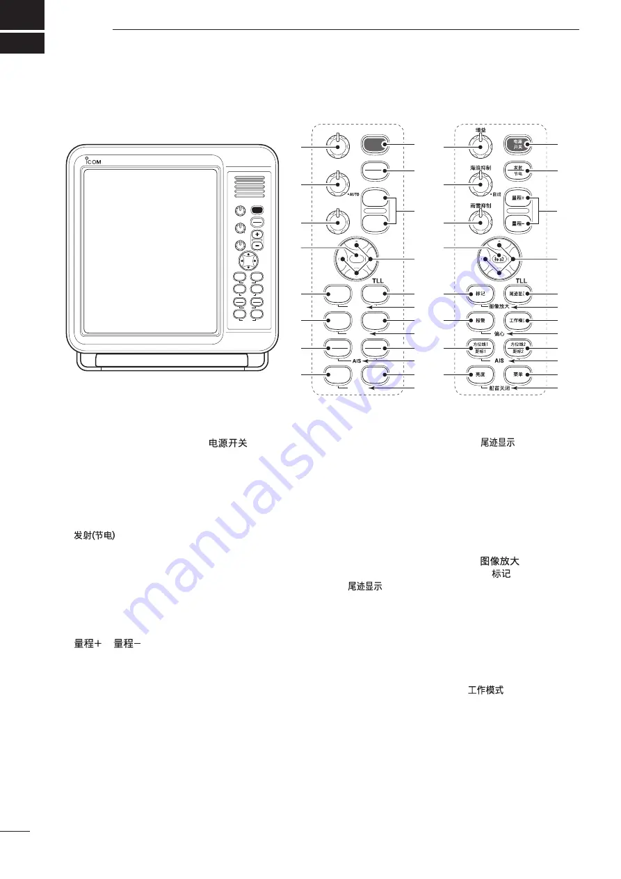
q

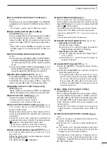
 POWER SWITCH [POWER]/[

(p. 9)

  Push to turn the radar power ON or OFF.

  •  The standby screen appears for 90 seconds while the 

magnetron warms up. 

  •  The initial screen appears and a beep sounds after the 

power has been turned ON.

w

  TRANSMIT/SAVE SWITCH [TX (SAVE)]/ 

[


  Push to toggle between the TX mode and the 

standby mode. (p. 9)


  Hold down for 1 second to turn ON the power 

save function. The radar for TX interval scan is 
fixed at 10 revolutions. (p. 12)


• Select the save time in the INT. SETTING menu.

e

  RANGE UP/ DOWN SWITCHES [+]/[–]/ 

[

]/[

(p. 9)

  Push [

+

] to


increase the screen range. 

  Push [

] to decrease the screen range.

r

 UP, DOWN, LEFT, RIGHT KEYS [

p

] [

q

] [

t

] [

u

]


Set the EBLs, VRMs, alarm area, ATA target, AIS 
target and so on.

   In the Menu screen, push [

p

] or [

q

] to select the 

menu items, and then push [

t

] or [

u

] to select the 

option or set the value.

   In the normal operating mode, push a combination 

of the [

p

]/[

t

] or [

p

]/[

u

], or [

q

]/[

t

] or [

q

]/[

u

] to 

move the cross line cursor to the upper left or right, 
or lower left or right.

t

 TRAILS SWITCH [TRAILS]/[

(p. 12)


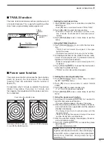
  Push to toggle the trail function ON or OFF. This 

is useful for watching other ship’s tracks, and ap-
proximate relative speed.


• Trail Time can be set in the VIDEO menu.


  Hold down for 1 second to output the position 

information where the cursor is placed, to the 
NMEA output terminals. 

      •  TLL output requires bearing data and position data.

y

 ZOOM FUNCTION [ZOOM]/[

(p. 11)

   Simultaneously push [TARGET]/[

] and [TRAILS]/

[

] to toggle the ZOOM function ON or OFF. 

The ZOOM function enlarges the target to two times 
normal size.


• Move the cursor to the target, then turn ON the function.


•  The screen zooms the middle of the screen around your 

own ship.


•  This function is not usable in the 

1

8

 and the 32 NM or 

higher ranges.

u

 MODE SWITCH [MODE]/[

]


Push to select the Head-up (H UP), Course-up (C 
UP), North-up (N UP) or True motion (TM) screens. 


•  The North-up and Course-up screens can be selected 

only when a bearing data input is connected. (pp. 28, 
43)


•  The TM screen requires bearing data and LOG or posi

-

tion data. (pp. 28, 43)


•  TheTM screen is not selectable in the 32 NM or higher 

range.

TX

SAVE

TARGET

TRAILS

MODE

ALM

+

-

MOB

MENU

EBL2

VRM2

EBL1

VRM1

BRILL

ZOOM

OFF CENT

HL OFF

GAIN

SEA

RAIN

POWER

MOB

GAIN

SEA

RAIN

POWER

TX

SAVE

TARGET

TRAILS

ZOOM

ALM

MODE

OFF CENT

EBL1

VRM1

BRILL

MENU

HL OFF

EBL2

VRM2

AIS

TLL

AUTO

MARINE RADAR

MR-1200

e

r

q

w

t

u

o

!1

y

i

!2

!3

!4

!5

!6

!7

!8

!9

@0

e

r

q

w

t

u

o

!1

y

i

!2

!3

!4

!5

!6

!7

!8

!9

@0

!0

!0

Control panel (English)

Control panel (Chinese)

Содержание MR-1200RII

Страница 1: ...INSTRUCTION MANUAL MARINE RADAR MR 1200R Radome type MR 1200T Open array type 4 kW MR 1200T Open array type 6 kW ...

Страница 2: ...ounding terminal 1 2 Ferrite EMI filter 1 SX 3230 12 1 inch LCD display unit Qty q Front cover 1 w NMEA connector PLT 167 P R 1 e NMEA connector PLT 168 P R 1 r Spare fuse FGB 15 A 1 t Spare fuse FGB 5 A for over 24 V power supply 1 y DC power cable 1 u Mounting bracket 1 i Mounting knob bolts 2 o Installation bolts M6 30 5 0 Installation nuts M6 5 1 Spring washers M6 10 2 Flat washers M6 10 3 Ins...

Страница 3: ...ectric shock may occur CAUTION Equipment damage may occur NOTE If disregarded inconvenience only No risk of personal injury fire or electric shock Icom Icom Inc and the Icom logo are registered trademarks of Icom Incorporated Japan in Japan the United States the United Kingdom Germany France Spain Russia and or other countries BE CAREFUL SART signals may not be detected and may not be displayed on...

Страница 4: ...because of possible damage to the case or the waterproof seals The LCD display may have cosmetic imperfections that appear as small dark or light spots This is not a malfunction or defect but a normal characteristic of LCD display For Scanner unit R DANGER HIGH VOLTAGE NEVER open the scanner unit The scanner unit contains high volt age that could be fatal And there are no user adjust ment points A...

Страница 5: ...ots ATA 20 AIS Automatic Identification System 21 AIS settings 22 AIS operation 23 Status of the Vessel icon 24 Plots AIS 24 7 BASIC RADAR THEORY 25 27 Side lobe echoes 25 Indirect echoes 25 Multiple echoes 26 Minimum range 26 Blind and Shadow sectors 27 Target resolution 27 8 INSTALLATION AND CONNECTIONS 28 34 Connecting the units 28 Power source requirement 28 Ground connection 28 Installing the...

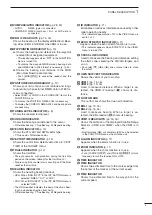
Страница 6: ...ap proximate relative speed Trail Time can be set in the VIDEO menu Hold down for 1 second to output the position information where the cursor is placed to the NMEA output terminals TLL output requires bearing data and position data y ZOOM FUNCTION ZOOM p 11 Simultaneously push TARGET and TRAILS to toggle the ZOOM function ON or OFF The ZOOM function enlarges the target to two times normal size Mo...

Страница 7: ...ter clockwise to deacti vate the RAIN function The RAIN indicator disappears 6 MAN OVERBOARD MOB Push to mark the man overboard point on the screen When a crew member falls overboard hold down MOB for 1 second to display the MOB symbol on the screen The MOB readout shows the bearing distance and es timated time to the MOB point at the current speed Hold down MOB for 1 second to cancel the function...

Страница 8: ...n 0 ALARM ZONE p 17 Shows the alarm zone Appears when the alarm function is in use 1 WAYPOINT MARKER p 13 Shows the waypoint received from navigation equip ment This marker appears when WPT in the FUNCTION menu is turned ON To display the waypoint marker bearing data and NMEA data in 0183 format is necessary p 43 2 FIXED RANGE RINGS p 14 Shows the distance at fixed intervals The interval distance ...

Страница 9: ...Shows the heading bearing readout HDG When BRG INPUT in the INT SETTING menu is selected NMEA N 1 or AUX COG When BRG INPUT in the INT SETTING menu is selected GPS The HDG readout indicates the bow of the ship s bear ing in a clockwise direction from north R Relative bearing T True Bearing M Magnetic bearing 5 IR INDICATOR p 11 Eliminates or reduces interference caused by other radar operating nea...

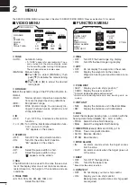
Страница 10: ... D TRAIL TIME 6S 15S 30S 1M 3M 6M 15M or Select the trail time FUNCTION MENU FUNCTION MENU POSN DISP WPT ON DIST UNIT BRG DIRECTION ZONE ALARM BEEP MAG PT SB KM OUT ON OFF CURS NM TRUE TRUE IN RING OFF ON OWN VECT ON OFF SHIP 360 R OFF D RING OFF Turn OFF the fixed range ring display ON Turn ON the fixed range ring display D WPT OFF Do not display the waypoint on the screen ON Display the waypoint...

Страница 11: ...herefore the CPA Closest Point of Ap proach and TCPA Time to CPA data may not be correctly calculated If a vessel is anchored in your alarm zone the unreliable data can cause the collision alarm to sound many times even if there is no real danger To prevent this when the anchored vessel s SOG Speed Over Ground is less than this set value the Slow Warn function assumes that vessel s COG is fixed to...

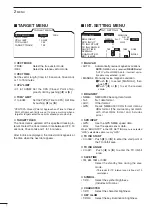
Страница 12: ...0M LOG 6M 15M MANUAL AUTO N 1 AUX GPS GPS 0 0 KEY ILLUM MAG VAR 1 2 3 1 2 3 1 2 3 4 0 0 W 1M D MAG VAR AUTO Automatically revise magnetic variations NOTE NMEA data is required NEVER select AUTO without NMEA data incorrect varia tion data may entered p 43 MANUAL Manually revise magnetic variation q Push u to select MANUAL then push q w Push t or u to set the revised value D BRG INPUT NMEA NMEA0183 ...

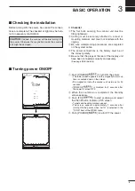
Страница 13: ...or details Turning power ON OFF 1 0 25 T VECT 6M 0 000NM NM CURS SOG17 7KT H UP 000 0 T HDG253 4 T E B L 1 E B L 2 MOB V R M 1 V R M 2 CURS 3 4 3 7 7 2 N 1 3 5 3 4 4 2 E STBY IR COMPASS GPS 1 0 25 T VECT 6M 0 000NM NM CURS SOG17 7KT H UP 000 0 T HDG253 4 T E B L 1 E B L 2 MOB V R M 1 V R M 2 CURS 3 4 3 7 7 2 N 1 3 5 3 4 4 2 E IR COMPASS GPS 0 45 R E V ROM OK RAM OK q Push POWER to turn ON the powe...

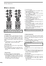
Страница 14: ... the desired target is located under the heading marker Simultaneously hold down BRILL and MENU to hide the heading marker D Fixed range rings The fixed range rings can be used for rough distance measurements p 14 Push MENU to open the FUNCTION menu then push q to select RING Push u to turn ON the ring D Manual tuning The receiver tuning can be manually adjusted Push MENU to open the VIDEO menu th...

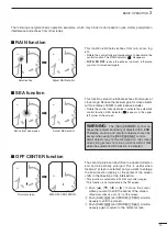
Страница 15: ...r of the screen OFF CENTER function With OFF CENTER ON Normal screen The scanning area can be shifted in a desired direction and can be partially enlarged This is useful when Head up screen is selected and you want to enlarge the bow direction display or the center of the screen shifts in the direction of the intersection This function is selectable in 24 NM or shorter ranges This function is not ...

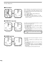
Страница 16: ...e magnified electronically for easier viewing of small targets p 5 q Push MENU one or more times to select the VIDEO menu w Push q to select STRETCH then push u to turn ON the function ES appears in the upper right of the screen when the function is activated NOTE Turn OFF this function during normal opera tion ZOOM function With ZOOM function ON Normal screen The ZOOM function expands the target ...

Страница 17: ...0 revolutions then stops for 1 minute and then repeats this sequence while the power save func tion is activated CURS 3 4 3 7 7 2 N CURS 3 4 3 7 7 2 N 1 0 25 T VECT 6M 0 900NM NM CURS SOG17 7KT H UP 014 6 T HDG273 9 T IR ES E B L 1 E B L 2 MOB V R M 1 V R M 2 1 3 5 3 4 4 2 E 0 48 SAVE Hold down TX for 1 second to turn ON the SAVE function Scan and STBY alternates Count down the standby time 1 0 25...

Страница 18: ...ng pulse function To magnify the blips for easier viewing of small tar gets the long pulse and echo stretch p 11 functions are usable When the long pulse is used in the 3 4 to 3 NM range this function magnifies target echoes to the backward direction of the target Pulse selection q Push MENU one or more times to select the VIDEO menu p 5 w Push q one or more times to select PULSE e Push t or u to ...

Страница 19: ... 2 2 4 4 8 8 6 64 72 4 6 12 16 1 20 1 20 1 10 1 4 1 4 1 4 1 2 1 2 NOTE When the screen is shifted the number of rings may differ Available for the MR 1200TII TIII Available for the MR 1200TIII only D Using the variable range marker q Push EBL1 VRM1 to display VRM1 and EBL1 then push p or q to set the marker The range between the ship and the target is indicated in the VRM readouts w Push EBL2 VRM2...

Страница 20: ...get bear ing and distance The EBL readouts indicate the target bearing 0 to 360 R Relative direction when 360 R is se lected in the DIRECTION item of the FUNCTION menu See page 5 P S 0 to 180 Bow direction when PT SB is selected in the DIRECTION item of the FUNC TION menu See page 5 0 to 360 T True or magnetic bearing when select ing TRUE in the DIRECTION item of the FUNCTION menu See page 5 Beari...

Страница 21: ...IR ES EBL1 EBL2 WPT VRM1 VRM2 3211 T 1714 T 0401NM 0184NM POSN VRM2 EBL2 EBL1 VRM1 q Push TRAILS p 12 to turn ON the TRAILS function then wait until the trail time count up reaches to the TRAIL TIME w Set VRM1 and EBL1 to a previously plotted target as described above e Set VRM2 and EBL2 to the current plotted position of the same target as described above r The VRM2 readout is a measure of target...

Страница 22: ...ne The selected alarm zone appears t Push ALM to set the alarm zone and acti vate the alarm function ALM appears on the bottom of the screen The selected alarm zone remains y If a target comes into or goes out of the alarm zone an alarm sounds Push ALM to cancel the alarm signal and func tion u To deactivate the alarm function push ALM ALM and alarm zone disappear from the screen i To activate the...

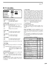
Страница 23: ...y the calculated true or relative course and speed The vector line is displayed on the target ATA AIS MENU ATA No DISP OFF ALL ON OFF ATA ALARM ON OFF AIS DISPLAY ON OFF AIS ALARM ON OFF AIS RANGE 8 0NM AUTO ACTIVATE 1 0NM NUMBER OF AIS 100 SLOW WARN 0 1KT LOST AIS TRGT ERASE SEL ATA ATA settings D ATA AIS menu Set the menu items before using the ATA function q Push MENU one or more times to selec...

Страница 24: ...a desired target w Hold down TARGET for 1 second to select the target for tracking A dotted square symbol appears on the cursor The target identification number bearing distance read out course CSE speed SPD CPA and TCPA appear in the information screen The timer starts to count the progressing time After 20 seconds progressing time has passed the vec tor appears on the target After 1 minute progr...

Страница 25: ...s 5 dots during each specified tracking interval The target track may change depending on the TARGET TRACK setting see TARGET menu pp 7 19 q Target goes straight w Target turns right e Target reduces speed dots are closer together behind the target r Target increases speed dots are father apart be hind the target Plotting marks There are 5 kinds of plotting marks Selected uncalculated mark Selecte...

Страница 26: ...Selected AIS target A square of only four corners appears when the tar get is selected The selected AIS target s information is displayed in the data area AIS indicator Appears when a valid VDM sentence is input from the NMEA AIS port If more than the specified AIS signals that is set in the NUMBER OF AIS setting of the ATA AIS menu are received this indicator changes to a reverse dis play AIS The...

Страница 27: ...get into an activated target OFF Turns OFF the Auto Activate function 0 1 to 9 9 NM Select the distance from your vessel NUMBER OF AIS Select the maximum number of AIS targets that can be displayed on the screen to between 10 and 100 SLOW WARN The AIS unit calculated COG Course Over Ground data of a vessel that is at anchor or drifting is unre liable and therefore the CPA Closest Point of Ap proac...

Страница 28: ...he AIS data area AIS Class MMSI number bearing distance Course Over Ground COG Speed Over Ground SOG CPA and TCPA appear The position information and Vessel name are alter nately displayed If several targets are overlapped on the screen push TARGET to sequentially select a target Hold down TARGET for 1 second to toggle the selected target between activated and sleeping Push EBL1 VRM1 and EBL2 VRM2...

Страница 29: ...ed target The target is displayed with the heading line SOG Speed Over Ground COG Course Over Ground vector and ROT Rate of Turn Dangerous target Even if the target s status is sleeping or acti vated when it enters your CPA and TCPA limit settings the target is displayed with a thick line Selected target The target s information is displayed in the data area Lost target When the AIS signal has not...

Страница 30: ...of the beam inside the lobes If a target reflects this radiation it will be displayed on the screen as an echo Main beam Side lobes Side lobe echoes usually occur at short ranges and as a result of large strongly reflective targets They can be reduced with proper adjustment of the SEA control See page 9 for the SEA control False echoes True echo Radar uses a form of electromagnetic radiation which...

Страница 31: ...e Detection at short range is very important Minimum range is determined primarily by transmitter pulse length vertical beam width and height of the scanner unit The shorter the transmission time the quicker the return echoes can be received and their distance mea sured The ability to see targets very close to the ship is de creased if the scanner is mounted too high off the water because the bott...

Страница 32: ... Your ship Large island Small island Target resolution Target resolution is determined by the horizontal beam width and transmit pulse width Sometimes it is difficult to detect two targets which are separated by short dis tances or which are in the same direction D Distance resolution When two targets are separated by more than the pulse width they appear as two echoes When two targets are not sep...

Страница 33: ...und The display unit is designed for connection to any power source if the voltage is 10 2 42 V DC so that a 12 24 or 32 V DC battery can be used without a DC DC converter or any internal modifications DC power cable connection CAUTION Incorrect cable connection will dam age the display unit Connect the supplied DC power cable as shown in the diagram Ground connection To prevent electrical shocks ...

Страница 34: ...S SAFE DISTANCE stated in the se rial number label on the rear panel away from the compass and navigation receiver Select a position where there is no danger of salt or fresh water spray or immersion Select a location where it is easy to perform mainte nance or adjustment after installation Select a location which can support the weight of the display unit DO NOT select areas subject to extreme he...

Страница 35: ...should be placed as high as possible on the boat to obtain best performance with maximum range If you install two or more radar in one boat install one above and the other s below The mounting surface must be parallel with the boat s waterline If the height is insufficient to install the scanner unit build a special frame for installation D Mounting q Drill four holes 12 mm 0 47 in in diameter usi...

Страница 36: ...unit assembly cover removed y Connect the power cable black and red to the power connector t u Tighten the sealing nut then replace the radome cover over the scanner unit DO NOT stretch the system cable too much other wise a miss contact of the connector may occur i Tighten the four bolts on the bottom of the scanner unit Use a torque wrench until the scale on the wrench reads 5 0 N m 3 69 lbf ft ...

Страница 37: ... should be placed as high as possible on the boat to obtain best performance with maximum range If you install two or more radar in one boat install one above and the other s below The mounting surface must be parallel with the boat s waterline If the height is insufficient to install the scanner unit build a special frame for installation D Mounting q Drill four holes 12 mm 0 47 in in diameter us...

Страница 38: ...ed cable tie y t Connect the shielded cable ground wire to the chas sis with the screw as shown in the diagram u y Clamp the system cable with the cable clamp metal fitting using a screw near the sealing connector i Be sure to clamp it tightly u Clamp the system cable with the ferrite EMI filter attached near the sealing connector o Be sure to clamp it tightly Secure the ferrite EMI filter with ca...

Страница 39: ...red Manufacture ESSO Type BEACON 325 e Connect a grounding wire purchase locally to the ground plate with the supplied terminal if required Fig 2 NOTE When using the optional system cable Peel the outer sheath of the system cable when using the optional system cable OPC 1078A BE CAREFUL DO NOT cut the inner shield wire when peeling the outer sheath Unit mm inch Peel the sheath To the display To th...

Страница 40: ...he power to display the test pattern To return to normal operating mode turn OFF the power then turn it ON again D Simulator screen The MR 1200RII TII TIII has simulator screen capabil ity q While holding down BRILL push POWER to turn ON the power w After the count down ends the standby screen ap pears e Push TX SAVE to display the simula tor screen r To return to normal operating condition turn O...

Страница 41: ...4 12 16 24 32 36 72 48 64 D TIMING ADJ Corrects the distance D HDG ADJ Adjusts the electronic heading line adjustment D SPD ADJ Enter the pulse rate of the speed sensor D RANGE 1 8 1 4 1 2 3 4 1 1 5 2 3 4 6 8 12 16 24 32 36 48 64 72 Choose the selectable screen range MR 1200TII TIII MR 1200TIII only D SETUP MEMORY The present value is displayed by pushing u then select the desired item from RECALL...

Страница 42: ...ion may be helpful when the scanner has not been mounted exactly in the line with the bow q Line up the bow of the boat with an identifiable tar get w Push TX SAVE to display the target on the screen e Push MENU one or more times to select the SERVICE MAN menu r Push q one or more times to select HDG ADJ t Push t or u to adjust until the target matches the heading marker the difference can be read...

Страница 43: ...PUT ENGLISH VOLTAGE MG 3 4 0 7 5 3 0 0 5 5 TIMING ADJ 1 8 3 4 2 6 1 4 1 3 8 1 2 1 5 4 12 16 24 32 36 48 RANGE 1 4 NM range will be skipped 72 64 q Push MENU q and u to display the SERVICE MAN menu w Hold down q until the RANGE section becomes highlighted e Push p or q to choose the selectable screen ranges with or on the dis play r Push t to skip from the range selection or push u to cancel skippi...

Страница 44: ...MALFUNCTION AIS GENERAL FAILURE AIS MKD CONNECTION LOST AIS EXTERNAL EPFS LOST AIS NO SENSOR POSITION IN USE AIS NO VALID SOG INFORMATION AIS NO VALID COG INFORMATION AIS HEADING LOST INVALID AIS NO VALID ROT INFORMATION Only the first 29 digits of the error message are displayed If the message is longer than 30 digits is displayed after the 29th digit Message Condition BRG INPUT FAIL 1 The Azimut...

Страница 45: ...he painted surface of the upper scanner unit will cause a consider able drop in radar performance e Check for cracks or deterioration of the rubber pack ing and replace it if necessary D Painting MR 1200TII TIII To prevent the corrosion paint the surface of the scanner body except the antenna unit twice a year or more D Mounting Check the mounting bolts of the scanner unit and tighten if necessary...

Страница 46: ...III optional for MR 1200RII 30 m 98 4 ft optional D Display unit LCD display 12 1 inch TFT LCD display Pixels 600 800 dot LCD mounting Vertical Input NMEA 0183 format for navigation receiver N 1 format fluxgate compass sensor AUX IEC61162 2 format for AIS unit Output NMEA 0183 format Power supply requirement 10 2 to 42 V DC Power consumption at zero wind velocity Approximately 60 W MR 1200RII Appr...

Страница 47: ...mately 8 kg 17 5 lb without cable EX 2780 Open array Type 120 cm 4 ft Slotted Waveguide Array Rotation speed typical 22 rpm MR 1200TIII only 24 rpm 36 rpm Beam width typical Horizontal beam 2 Vertical beam 25 Side lobe typical 24 dB Polarization Horizontal Transmission frequency 9410 MHz 30 MHz P0N Peak output power 4 kW MR 1200TII 6 kW MR 1200TIII Pulse width 80 ns 2160 Hz 80 ns 1440 Hz 250 ns 14...

Страница 48: ...LL or GNS AIS CPA TCPA Alarm OG 1 AIS Required VDM RMC or VTG RMC GGA GLL or GNS TW 1 AIS Required VDM LOG RMC GGA GLL or GNS Alarm status 4 ALR EXTERNAL DATA OUTPUT NMEA2 2 connector RMC GGA GLL VTG TTM TLL RSD 1 G Over ground TW Through the water 2 NMEA1 and NMEA2 connectors see page 28 3 AIS input also receives RMC GGA GLL VTG and GNS sentences If the NMEA2 input does not receive these the sent...

Страница 49: ...99 8 mm 3 15 16 in 199 6 mm 7 27 32 in 256 mm 10 3 32 in Radius is 3 5 mm 1 8 in Radius is 3 5 mm 1 8 in 31 mm 1 7 32 in 62 mm 2 7 16 in 92 mm 3 5 8 in SX 3230 Display mounting bracket template ...

Страница 50: ......

Страница 51: ...Ship s bow direction Radius is 6 mm 1 4 in EX 2714 Radome template 90 5 mm 39 16 in 90 5 mm 39 16 in 150 5 mm 515 16 in 45 5 mm 125 32 in ...

Страница 52: ......

Страница 53: ...Ship s bow direction EX 2780 Open array type template 131 mm 55 32 in 131 mm 55 32 in 190 mm 715 32 in Radius is 6 mm 1 4 in ...

Страница 54: ......

Страница 55: ......

Страница 56: ...1 1 32 Kamiminami Hirano ku Osaka 547 0003 Japan A 7071H 1EX Printed in Japan 2013 Icom Inc Printed on recycled paper with soy ink ...

Отзывы: