iv
SYSTEM COMPONENTS ......................................... i
SUPPLIED ACCESSORIES ...................................... i
FOREWORD ............................................................ ii
IMPORTANT ............................................................. ii
EXPLICIT DEFINITIONS .......................................... ii
PRECAUTIONS ....................................................... iii
TABLE OF CONTENTS ........................................... iv
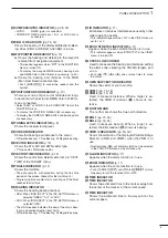
1 PANEL DESCRIPTION .................................. 1–4
■
Front panel ...................................................... 1
■
Screen ............................................................ 3
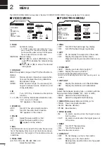
2 MENU ............................................................. 5–7
■
VIDEO MENU .................................................. 5
■
FUNCTION MENU........................................... 5
■
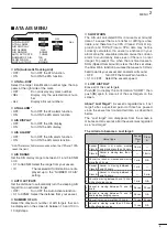
ATA AIS MENU ................................................ 6
■
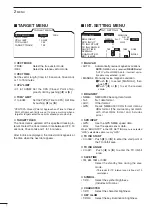
TARGET MEMU ............................................... 7
■
INT. SETTING MENU ...................................... 7
3 BASIC OPERATION .................................... 8 –13
■
Checking the installation ................................. 8
■
Turning power ON/OFF .................................... 8
■
Basic operation ............................................... 9
■
RAIN function................................................. 10
■
SEA function .................................................. 10
■
OFF CENTER function .................................. 10
■
IR function ..................................................... 11
■
STRETCH function ....................................... 11
■
ZOOM function ............................................. 11
■
TRAILS function ............................................ 12
■
Power save function ...................................... 12
■
Ship speed indication .................................... 13
■
Position indication ......................................... 13
■
Waypoint indication ........................................ 13
■
Long pulse function........................................ 13
■
Bearing setting .............................................. 13
4 DISTANCE AND DIRECTION
MEASUREMENTS ..................................... 14–16
■
Distance measurement ................................. 14
■
Bearing and Distance measurement ............ 15
■
Advanced measurements ............................. 16
5 ALARM FUNCTION ......................................... 17
■
Alarm zone setting ........................................ 17
■
Zone alarm setting ........................................ 17
6 ATA/AIS ...................................................... 18–24
■
ATA (Automatic Tracking Aid) ........................ 18
■
ATA settings .................................................. 18
■
ATA operation ................................................ 19
■
Plotting marks ............................................... 20
■
Course and speed vector .............................. 20
■
Plots (ATA) ..................................................... 20
■
AIS (Automatic Identification System) .......... 21
■
AIS settings ................................................... 22
■
AIS operation ................................................ 23
■
Status of the Vessel icon ................................ 24
■
Plots (AIS) ..................................................... 24
7 BASIC RADAR THEORY .......................... 25– 27
■
Side-lobe echoes .......................................... 25
■
Indirect echoes ............................................. 25
■
Multiple echoes ............................................. 26
■
Minimum range ............................................. 26
■
Blind and Shadow sectors ............................ 27
■
Target resolution ............................................ 27
8 INSTALLATION AND CONNECTIONS ..... 28–34
■
Connecting the units ..................................... 28
■
Power source requirement ............................ 28
■
Ground connection ........................................ 28
■
Installing the display unit ............................... 29
■
Mounting the EX-2714 scanner unit ............. 30
■
Wiring the EX-2714 system cable ................. 31
■
Mounting the EX-2780 scanner unit ............. 32
■
Wiring the EX-2780 system cable ................. 33
■
Attaching the EX-2780 scanner unit ............. 34
9 OTHER FUNCTIONS ....................................... 35
10 SERVICE MAN MENU ............................... 36–38
■
Service man menu ........................................ 36
■
Select the language ...................................... 36
■
TIMING adjustment ....................................... 37
■
HDG adjustment ............................................ 37
■
SPD adjustment ............................................. 38
■
RANGE selection ........................................... 38
11 ERROR MESSAGE .......................................... 39
■
Error message list ......................................... 39
■
AIS error message list .................................. 39
12 MAINTENANCE ................................................ 40
■
Periodic maintenance ................................... 40
■
Scanner unit maintenance ............................ 40
■
Display unit maintenance .............................. 40
■
Options ......................................................... 40
13 SPECIFICATIONS ...................................... 41–42
14 EXTERNAL DATA LIST ................................... 43
(Supplement) TEMPLATE
■
Template for the display unit
• SX-3230 (Display mount bracket template)
■
Template for the scanner unit
• EX-2714
• EX-2780
TABLE OF CONTENTS

