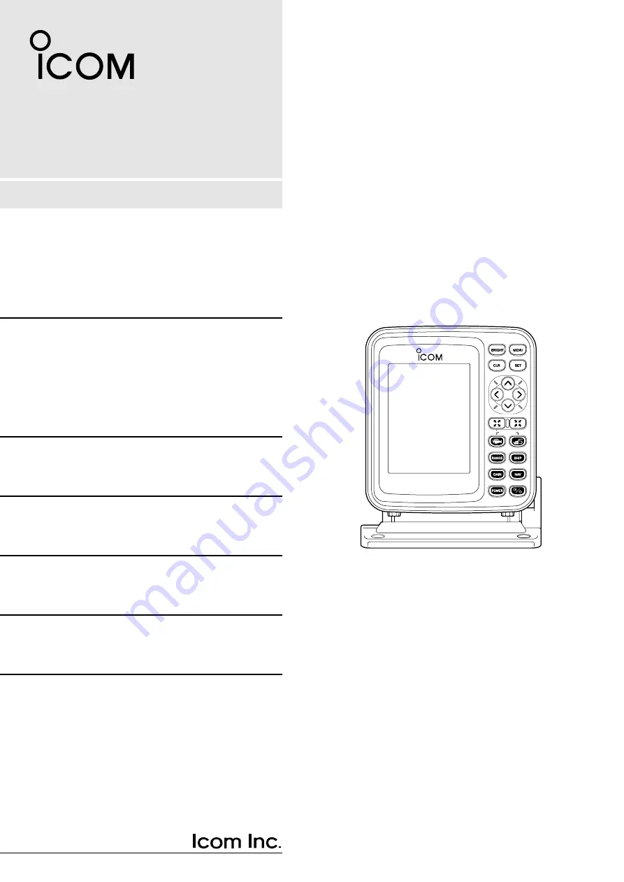
background image

Information provided by this
product includes navigation-aid
data.
Consult nautical charts in addi-
tion to the data when making a
decision on navigation.

MARINEPLOTTER/SOUNDER

fp-561


COMBINE

Electronic charts are not legal
replacements for paper charts.
Always carry and consult current
official charts frequently.

FP-561

MARINE PLOTTER/SOUNDER

INSTRUCTION MANUAL

Содержание FP-561

Страница 1: ...cal charts in addi tion to the data when making a decision on navigation MARINEPLOTTER SOUNDER fp 561 COMBINE Electronic charts are not legal replacements for paper charts Always carry and consult current official charts frequently FP 561 MARINE PLOTTER SOUNDER INSTRUCTION MANUAL ...

Страница 2: ...nnecting the PD 200 a DGPS beacon receiver to this system will permit the GPS to pinpoint the ship location more accurately Please read this instruction manual carefully to en sure correct and efficient use of the product SUPPLIED ACCESSORIES Instruction manual Cartgraphy supplied by NAVIONICS Seamless chart start from 99 and span the globe with high detail and 16 zoom levels Ask your nearest NAVI...

Страница 3: ...ce and ship speed 63 5 4 SETTING Correcting Plotter and Sounder parameters 63 AUTO GAIN FRAFT ADJUST TEMPERATURE ADJUST DATUM BEARING COMPASS INDICATION TIME REFERENCE OFFSET TIME SPEED DATA SPEED ADJUST NMEA OUT BOD OUT 5 5 RANGE SELECTION Registering depth ranges 67 5 6 ALL RESET Restoring the original settings 67 6 INSTALLATION PROCEDURE 68 6 1 Overall connection diagram 68 6 2 Installation pro...

Страница 4: ...ctric shock or leak Be careful to prevent foreign objects from entering the product Foreign objects including metal chips wire scraps and liquids inside the product may cause a shortcircuit fire or malfunction A through the hull type echo sounding transducer must be installed by a shipbuilder or an expert installer Otherwise the ship could be waterlogged RWARNING Each of the following caution noti...

Страница 5: ...e before powering on the product Avoid using organic solvents such as thinner or benzene to clean the product These solvents will cause damage to the product sur face To clan the product or antenna wipe it using a soft cloth damped with a water diluted detergent The product contains a lithium battery having a life of approx five years which retains GPS positioning data If this backup battery is co...

Страница 6: ...2 PARTS AND FUNCTIONS 3 Main unit MARINEPLOTTER SOUNDER FP 561 COMBINE 5 0 4 3 2 o i t r e w q u y 1 Tilting lever COMBINE Operation panel ...

Страница 7: ...r DOWN RIGHT key combination allows you to move the cross hair cursor to the lower left or right Use to delete marks or abort setting on various screens Use to adjust the brightness and contract P 5 of screen display Use to select the menu screen P 7 Use to execute operations or save settings Use to zoom out the coastline screen image P 18 This key can also be used to zoom out the bottom rock scre...

Страница 8: ...er approx 10 seconds 8 GPS 48 21 417N 125 26 643W 57 6 FT CONT BRIGHT CLR SET SET CANC ADJ SEL ADJ ADJ The LCD can be adjusted in brightness and contrast according to the envi ronment of the installation site q Press the BRIGHT key A level bar indicating the LCD brightness and contrast will appear at the lower left of the screen w Press the LEFT or RIGHT key to select setting item Brightness or Co...

Страница 9: ...ve to the standard screen of the fishfinder mode or the coastline screen of the plotter mode Plotter mode Combination Sounder mode Coastline screen Navigation monitor screen L O N L A T 60 90 30 15 R 30 0 60 90 DEVIATION 0 0 3 NM 1 2 4 2 3 1 6 5 W 4 8 5 0 7 0 5 N N E W NW NE Standard screen Standard A scope screen Combination mode Dual screen Standard Bottom lock screen Standard Marker zoom in scr...

Страница 10: ...ly select the desired digit using the LEFT or RIGHT key and enter or change the value using the UP or DOWN key then press the SET key t Repeat step r above for each setting item y Repeat steps e to t above for each submenu u When you finish setting press the CLR momentarily to close the Main Menu screen For detailed description of setting on each submenu screen see the appropriate section M A I N ...

Страница 11: ...stem before inserting or removing a Electronic Chart card into or from the card slot Insert a NAVIONICS Electronic Chart card carefully into the card slot with the card face on which is marked directed to the same direction as the display Forcing a Electronic Chart card into the slot will cause damage to the card socket in the slot If the system fails to operate normally even through an Electronic...

Страница 12: ...ON OFF POSITIONING MENU POS CORR GOTOCURSUR AVERAGING 1 OFF POSITIONING INFO DGPS LON E0 000 LAT N0 000 ALARM MENU DEPTH 1m OFF SHALLOW 1m OFF FISH DEPTH 1m OFF ALARM ZONE 0 01NM OFF M A I N M E N U POSITIONING MENU PLOTTER MENU ALARM MENU SOUNDER MENU GPS 48 21 417N 125 26 643W POS EQUIP GPS NMEA SCREEN MENU WIDTH 1m SCREEN SETTING LAND YELL CSLN BKG COLOR BLUE SEA BLUE NAME WHIT OFF D CON 5m LBL...

Страница 13: ...nt between two points specified with the cursor 19 3 ROUTE REGISTRATION AND EDIT 20 3 1 Registering and editing navigation routes 20 Å Registering navigation routes 20 ı Editing navigation routes 21 Extending a navigation route 21 Clearing turning points 21 3 2 Clearing a route 22 3 3 Character list 23 4 MARK MANIPULATION 24 4 1 Registering marks 24 Å Registration of marks from the Plotter Menu sc...

Страница 14: ...ying the color of land 31 ı Specifying the color of sea 31 Ç Specifying the color of place names 32 Î Specifying the color of depth contours 32 Specifying the color of lights 32 Ï Specifying the color of map border 33 Specifying the display mode 33 9 SELECTION OF POSITIONING DEVICE 34 10 CORRECTION OF SHIP POSITIONING ERROR 35 10 1 Correcting a ship positioning error 35 10 2 Correction using the c...

Страница 15: ...gation monitor screen Positioning Information screen 80 0 FT 0 T 12KT 54 3 F RANGE 32 2 0 1 8 DGPS 34゚18 000N 135゚01 000E TO WP 1 23 00NM 30 34 21 362N 28 135 06 950E 18 05 NM 1 32 80 0 FT 0 T 12KT 54 3 F LON LAT 60 90 30 345 15 R 30 0 60 90 14 25 01 05 15 30 TIME TTG ETA 15 30 TTFD W P No 1 D D C D D FD 10 45NM 10 45NM DEVIATION 0 03NM 134 01 000E 34 18 000N N E W NW NE 0 10 20 30 40 POSITIONING ...

Страница 16: ... received for 10 seconds or more due to a connection error The cross hair cursor appears on the screen when the UP DOWN or LEFT RIGHT key is pressed This mark shows the current ship position The ship is currently located at the cen ter of this mark This mark changes to when the ship slows down to 3 knots or equivalent in km h or Ml h or less This field shows the current depth of water 1 2 Coastlin...

Страница 17: ...ion No the destination azimuth relative to the current ship position the distance from the ship to the destination and the deviation out of course The deviation out of course is indicated graphically This field shows the intersection position of the cross hair cursor in latitude longi tude and the azimuth and distance of the intersection relative to the current ship position Aligning the intersect...

Страница 18: ...a green line and numer ically on the assumption that the destination azimuth is zero degree Note that although the deviation of the ship azimuth from the destination azimuth exceeds 90 degrees the reading remains 90 degrees This field shows the deviation out of course in distance graphically and numerical ly When alarm limits are set with the alarm function they are displayed with red lines on the...

Страница 19: ...n ranging from 0 00 to 99 99 P 38 The lower this value is the better the geometrical arrangement is for the system to receive signals from the satellites This field shows DGPS positioning information 1 4 Positioning Information screen 0 10 20 30 40 DGPS 34゚18 000N 135゚01 000E POSITIONING INFO SAT S N BRG ELV DOP DGPS INFOMATION RD 200 Rev 1 1 FREQUENCY 283 5kHz BAUD RATE 200 S N 00 1 50 BACK 12 50...

Страница 20: ... Using the DOWN LEFT or DOWN RIGHT key combination allows you to move the cross hair cursor to the lower left or right When the cross hair cursor reaches a screen edge the coastline image is scrolled e Use the ZOOM IN or ZOOM OUT key to enlarge or reduce the image to the desired scale in cursor centering mode When you press the SHIP key in cursor centering mode the cross hair cursor disappears and...

Страница 21: ...e Main Menu screen will appear w Select Screen Setting using the UP or DOWN key and press the SET key The Screen Setting screen will appear e Select GRID using the UP or DOWN key and press the SET key The selected menu item turns blue t Move to the color field using the LEFT key The color field is highlighted in yellow y Select the desired color from among available colors White WHIT Yellow YELL L...

Страница 22: ...the cursor position field When the ship mark coincides with the cursor position a message indi cating the ship reaches the cursor position is displayed in this field GPS 34゚18 000N 135゚01 000E 6 Cursor position field where the distance and azimuth between the ship and the cursor position are displayed 80 0 FT 0 T 12KT 54 3 F 34 20 000N 135 02 500E 27 2 35 NM 0 15 RANGE 8 80 0 FT 0 T 12KT 54 3 F GP...

Страница 23: ...me the SET key is pressed the selected character is entered in the comment field A comment such as a user defined route name of up to eight characters can be entered in each comment field i Select END and press the SET key The coastline screen will appear o Move the cross hair cursor to the beginning point of the route using the UP DOWN or LEFT RIGHT key and press the SET key Move the cross hair c...

Страница 24: ...finish extending the route press the MENU key The route extension is registered and you will return to the coastline screen Pressing the CLR key during extending a route clears the last turning point registered the mark is not cleared Repeat this operation until all the turning points you want to clear are cleared Clearing all the turning points of a route results in the route itself being cleared...

Страница 25: ...route No you selected is going to be cleared u Press the SET key again to clear the route i When you select ERSALL in step r above Press the SET key A message will appear at the bottom of the screen indicating all the registered routes are going to be cleared o Press the SET key again to clear all the routes GPS 34゚18 000N 135゚01 000E 5 Select ERS and press the SET key Select the route No you want...

Страница 26: ... No When a space is selected and the SET key is pressed a space is entered in over write mode in the comment field of the selected route No The cursor moves to the arrow direction you specified here Select the direction in which you want to move the cursor using the UP DOWN or LEFT RIGHT key and press the SET key Use this command when you finish or abort comment entry Select END using the UP DOWN ...

Страница 27: ...ction E East or W West using the UP or DOWN key and then press the SET key One of 12 marks will appear at the bottom of the screen u Select the desired mark using the UP or DOWN key and the desired color of the mark seven colors selectable using the LEFT or RIGHT key and then press the SET key The character list will appear at the bottom of the screen and END is highlight ed in yellow i Select a c...

Страница 28: ...ET key Selecting the desired mark and color Activating the cross hair cursor Entering a comment 80 0 FT 0 T 12KT 54 3 F RANGE 4 80 0 FT 80 0 FT 34 18 000N 135 01 000E 27 2 89 NM 0 15 34 18 000N 27 CLR SET SET CANC SEL END ABCDEFGHIJKLMNOPQRS TUVWXYZ 0123456789 abcdefghijklmnopqrs tuvwxyz CLR SET SET CANC TYPE COL COMMENT Point2 COM MENU q On the coastline screen press the UP DOWN or LEFT RIGHT key...

Страница 29: ...r the mark press the CLR key again r Press the SET key The mark will be cleared Note that while the cross hair cursor is not active on the screen the current ship position mark is not cleared GPS 34゚18 000N 135゚01 000E 5 Move the cross hair cursor until it coincides with the mark you want to clear and press the CLR key Clearing marks on the coastline screen Mark position data 80 0 FT CLR OK SET CA...

Страница 30: ...key Select route No and GO or RTN voyage and press the SET key Selecting a route No Route navigation screen Navigation screen 2 1 0 3 5 DGPS 34゚18 000N 135゚01 000E CLR SET SET CANC 80 0FT NAV SEL DESTINATN ROUTE CLR SET SET CANC 80 0FT ROUTE ROUTE 1 SEL 1 GO GO RTN TO WP 1 0 19NM 315 80 0 FT 0 T 5 5KT 54 3 F RANGE 4 The solid line indicating the first section of route navigation defaults to green ...

Страница 31: ...t DESTINATN and press the SET key Select a mark and press the SET key Navigation screen Destination navigation screen CLR SET SET CANC 80 0FT NAV SEL DESTINATN ROUTE CLR SET SET CANC 80 0FT DESTINATN 34 18 000N 135 01 000E Point2 27 2 89 NM 0 15 1 0 Destination navigation screen 5 DGPS 34゚18 000N 135゚01 000E Move the cursor to the desired position and press the SET key TO WP 1 1 40NM 50 80 0 FT 0 ...

Страница 32: ...ls allow the system to cover a longer track but may cause a lower resolution of the track image when zoomed in To change the tracking intervals proceed as follows q Press the MENU key The Main Menu screen will appear w Select Plotter Menu using the UP or DOWN key and press the SET key The Plotter Menu screen will appear e Select TRK STEP track step using the UP or DOWN key and press the SET key Th...

Страница 33: ... SET key The Plotter Menu screen will appear e Select FRONT WIDE using the UP or DOWN key and press the SET key The selected item turns blue r Select ON or OFF using the LEFT or RIGHT key and press the SET key The heading area will displayed widely when ON is selected t Press the MENU key to return to the previous screen To set the over zoom function proceed as follows q Press the MENU key The Mai...

Страница 34: ...ow YELL Light blue LBLU Purple PURP Red Green GREE Blue using the UP or DOWN key and press the SET key Land will be displayed in the selected color y When you finish setting the color of land press the MENU key You will return to the previous screen The color of sea can be selected from among two available colors q Press the MENU key The Main Menu screen will appear w Select Screen Setting using t...

Страница 35: ...y and press the SET key Depth contour will be displayed in the selected color When you select OFF and press the SET key depth contour are not dis played y When you finish setting the color of depth contour press the MENU key You will return to the previous screen The color of lights can be selected from among seven available colors q Press the MENU key The Main Menu screen will appear w Select Plo...

Страница 36: ...en you finish setting the color of map border press the MENU key You will return to the previous screen These color settings can be memorized and selected from two display modes q Press the MENU key The Main Menu screen will appear w Select Plotter Menu using the UP or DOWN key and press the SET key The Plotter Menu screen will appear e Select DISP MODE display mode using the LEFT or RIGHT key and...

Страница 37: ...he LEFT or RIGHT key The selected option is highlighted in yellow When you select GPS positioning data received by the supplied GPS receiv er is used to pinpoint the current ship position When you select NMEA positioning data received via the external NMEA input port is used to pinpoint the current ship position Selecting NMEA disables DGPS and Positioning Information to be selected t When you fin...

Страница 38: ...ments Orientation in latitude or longitude can also be changed from N North to S South or E East to W West and vice versa q Press the MENU key The Main Menu screen will appear w Select Positioning Menu using the UP or DOWN key and press the SET key The Positioning Menu will appear e Select POS CORR Position Correction using the UP or DOWN key and press the SET key GOTOCURSOR Goto Cursor Position i...

Страница 39: ...key and press the SET key The Positioning Menu screen will appear e Select Averaging using the UP or DOWN key and press the SET key The selected item turns blue r Move to the averaging level field This field will be highlighted in yellow t Enter a value into the averaging level field using the UP or DOWN key and press the SET key A higher averaging level results in smaller meandering of the track ...

Страница 40: ...and press the SET key The Positioning Menu screen will appear e Select DGPS using the UP or DOWN key and press the SET key The DGPS screen will appear r Select Beacon Frequency using the UP or DOWN key and press the SET key The selected item turns blue t Select the frequency field or Auto When you select the frequency field proceed with step y When you select Auto press the SET key When Auto is se...

Страница 41: ... will appear w Select Positioning Menu using the UP or DOWN key and press the SET key The Positioning Menu screen will appear e Select Positioning Info using the UP or DOWN key and press the SET key The Positioning Information screen will appear r Press the MENU key to return to the previous screen The DOP Dilution Of Precision is a positioning precision indicator which represents the geometrical ...

Страница 42: ...xt destination When the ship enters the alarm zone around the destination an arrival alarm is displayed and beeps are produced When the ship leaves the alarm zone around the destination a range alarm is displayed and beeps are produced When the ship deviates from the alarm zone during navigation a range alarm is displayed and beeps are produced When the ship enters the alarm zone around the destin...

Страница 43: ...urns blue To cancel the alarm function select OFF and press the SET key r Move to the alarm zone setting field using the LEFT or RIGHT key This field will be highlighted in yellow t Set a value into the alarm zone setting field using the UP or DOWN key and press the SET key The setting will be saved y When you finish setting the alarm zone press the MENU key You will return to the previous screen ...

Страница 44: ...41 ...

Страница 45: ... 52 10 SETTING OF DEPTH SHIFT 53 11 SELECTION OF AUTO OPERATION 53 12 DEPTH MEASUREMENT 54 13 SETTING OF ZOOM IN RANGE ON BOTTOM LOCK SCREEN 54 14 SETTING OF MARKER ZOOM IN RANGE 55 15 SETTING OF SOUNDER ALARM RANGES 55 16 HOW TO READ IMAGES 57 16 1 Reflections from the sea bottom 57 Å Reading topographical features of the sea bottom 57 ı Reading geological features of the sea bottom 57 16 2 Refle...

Страница 46: ...43 ...

Страница 47: ...l screen This screen shows two images of underwater that are detected at both of a high H and low L frequencies Frequencies set on the Fishfinder Menu screen are displayed on the right Standard Maker zoom in screen This function provides zoom in display around the variable range marker for detailed observation of underwater activity such as fish schools This screen consists of the standard screen ...

Страница 48: ...The depth marker green and depth value are indicated during depth measure ment This field shows the current depth of water If the level of reflections from the bot tom is low this may not be displayed This field shows the current water temperature ranging from 0 0 to 40 0 in C or 32 0 to 104 in F If the water temperature is out of this range is displayed If no water temperature sensor is installed...

Страница 49: ...levels When the Sensitivity key is pressed to adjust the sensitivity level the level bar appears on the screen while highlighted in yellow The color pattern consists of eight colors arranged in descending order of reflec tion level If the noise reduction function P 51 is ON however colors having a lower reflection level may not be displayed The background color can be set to Blue or Black P 50 The...

Страница 50: ...pe screen The A scope image represents reflections from the sea bottom or a shoal of fish in amplitude and color For common indications on differ ent screens such as alarm range marker time mark and sensitivity level see section 1 2 Standard screen Indicated in red due to large amplitude No change in color background color due to nothing detected Small amplitude Indicated in red due to large ampli...

Страница 51: ...40 60 80 0 100 z Depth marker x Maker zoom in image c Zoom in centerline This image is the same as that on the standard screen This image covers the specified bottom area P 54 z Standard image x Bottom lock image 1 5 Standard Bottom lock screen 0 10 5 H FT 57 6 315 T 10 2KT 58 F GPS 48 21 417N 125 26 643W z x 20 40 60 80 0 100 For common indications on differ ent screens such as alarm range marker...

Страница 52: ...under Menu using the UP or DOWN key and press the SET key The Sounder Menu screen will appear e Select STC using the UP or DOWN key and press the SET key The selected item turns blue r Enter the desired immunity level from among 15 levels using the UP or DOWN key and press the SET key The setting is now saved t When you finish setting the immunity level press the MENU key to close the Main Menu sc...

Страница 53: ... When you finish setting the display speed press the MENU key to close the Main Menu screen SOUNDER MENU DSP SPEED STC FT 43 4 I R N R L H 1 OFF OFF 5 STOP ON 1 CLR SET SET CANC ADJ SEL FREQUENCY GPS 48 21 417N 125 26 643W 20 40 60 80 0 100 Rate indication Rate STOP 1 5 Low b a High DISP MODE BKG COLOR LAND SEA NAME D CON 5m D CON 10m D CON 20m LIGHT GRID DISP MAPS SCREEN SETTING 1 2 BLUE YELL CSL...

Страница 54: ...e or green dots on fishfinder screens Default OFF To suppress the noises and make the image legible proceed as follows q Press the MENU key The Main Menu screen will appear w Select Sounder Menu using the UP or DOWN key and press the SET key The Sounder Menu screen will appear e Select N R using the UP or DOWN key and press the SET key The selected item turns blue r Move to the noise reduction lev...

Страница 55: ...ange manually proceed as follows q Press the RANGE key RANGE SHIFT or AUTO will be indicated in the depth field on the screen If auto operation is active it is canceled w Select RANGE using the LEFT or RIGHT key e Select the desired depth range using the UP or DOWN key Each time you press the UP or DOWN key the depth range changes in incre ments of one step On the Depth Range Selection screen P 67...

Страница 56: ...ration function of the system however permits the bottom image to be always displayed on the screen To use auto operation proceed as follows q Press the RANGE key RANGE SHIFT or AUTO will be indicated in the depth field on the screen w Select AUTO using the LEFT or RIGHT key e Press the RANGE or SET key to save the setting 11 Selection of Auto Operation H Depth field SHIFT CLR SET SET CANC SEL ADJ...

Страница 57: ... the depth marker to move continuously In Combination mode the depth marker cannot be used e To exit from the depth measurement mode select other fishfinder screens or press the CLR The zoom in range displayed on the standard bottom lock screen can be selected from among four options On the bottom rock screen a certain depth range measured from the sea bottom is zoomed in To set the zoom in range ...

Страница 58: ...zoom in range proceed as follows q Press the Sounder key to select Standard Marker zoom in Screen The depth marker will appear on the screen automatically w Pressing the UP or DOWN key move the depth marker to the desired posi tion In Combination mode the maker zoom in screen cannot be used e Press the ZOOM IN or ZOOM OUT key until the desired zoom in range is reached 14 Setting of Marker Zoom in ...

Страница 59: ... Main Menu screen To stop an alarm sound temporarily press the CLR key Depth alarm range Fish alarm range Shallow alarm range H 315 T 10 2KT 58 F FT 43 4 GPS 48 21 417N 125 26 643W 20 40 60 80 0 100 15 Setting of Sounder Alarm Ranges FT 43 4 ALARM MENU DEPTH SHALLOW FISH ALARM ZONE DEPTH WIDTH 85FT 15FT 0 4 NM OFF OFF OFF OFF 15FT 18FT CLR SET SET CANC SEL ADJ H GPS 48 21 417N 125 26 643W 20 40 60...

Страница 60: ...26 643W 20 40 60 80 0 100 20 40 60 80 0 100 315 T 10 2KT 58 F FT 43 4 GPS 48 21 417N 125 26 643W Topographical feature Flat Hilly Screen image Assuming that its geological features are constant the displayed contour of a flat terrain has a uniform width The displayed contour of a hilly terrain has a long tailing 1 This is because the ultrasonic sent from the transducer has a certain beam angle and...

Страница 61: ... it is radiated with the beam The relationship between the image size and the depth of an object depends on the image feed rate and the ship speed Larger fish school Smaller fish school H Radiated with the beam for a shorter time Radiated with the beam for a longer time 315 T 10 2KT 58 F FT 71 4 GPS 48 21 417N 125 26 643W 20 40 60 80 0 100 The higher the density of a fish school is the closer to r...

Страница 62: ...F FT 43 4 GPS 48 21 417N 125 26 643W 20 40 60 80 0 100 Tidal current layer H 315 T 10 2KT 58 F FT 43 4 GPS 48 21 417N 125 26 643W 20 40 60 80 0 100 Plankton layer H 315 T 10 2KT 58 F FT 43 4 GPS 48 21 417N 125 26 643W 20 40 60 80 0 100 Plankton may sometimes gather and form a layer Such a layer looks like a cloud on the screen and may expand to the depths Since plankton forms the food of many fish...

Страница 63: ...17N 125 26 643W 20 40 60 80 0 100 The side lobe from the transducer may cause phantom images These images tend to appear above the contour of the sea bottom in a hilly terrain or under the contour in a flat terrain 16 7 Phantom images Phantom images H Main lobe Side lobe 315 T 10 2KT 58 F FT 43 4 GPS 48 21 417N 125 26 643W 20 40 60 80 0 100 H 4 Voids due to air bubbles 315 T 10 2KT 58 F FT 43 4 GP...

Страница 64: ...is mode are the same as those in other modes except described below on this page In combination mode you cannot select other screens than shown above nor use the depth marker z x z Coastline screen x Sounder screen In combination mode the coastline screen is always displayed here In combination mode the standard screen is always displayed here 8 GPS 48 21 417N 125 26 643W RANGE 32 FT 43 4 0 T 10 2...

Страница 65: ...tart normal operation 5 2 Initial setting on each submenu screen Operation flow on the SET MODE screen S E T M O D E RANGE SELECTION SETTING ALL RESET UNIT TURN POWER OFF WHEN FINISHED UNIT DEPTH TEMP DISTANCE SPEED Km NM MI KT km h MI h MENU POWER Holding the MENU key down PUSH the POWER key m FT FM C F RANGE SELECTION UNIT m 5 3 5 4 5 5 SETTING AUTO GAIN DRAFT ADJ TEMP ADJ DATUM BEARING COMPASS ...

Страница 66: ...his section describes how to set the various parameters for plotter and sounder functions Select such units that are convenient for you to use This item allows you to make a selection between two automatic control options ON The image sensitivity and depth range are automatically controlled default OFF Only the depth range is automatically controlled The following describes how to correct for draf...

Страница 67: ...lighted in yellow r Enter the value corresponding to the nautical charts you currently use using the UP or DOWN key and press the SET key The setting is saved t When you finish setting geodetic data press the MENU key You will return to the SET MODE screen The following describes how to correct the ship or destination bearing that will be displayed on the coastline screen or other screens TRUE Tru...

Страница 68: ... the SET MODE screen using the UP or DOWN key and press the SET key The SETTING screen will appear w Select SPEED ADJ using the UP or DOWN key and press the SET key e Enter the pulse rate of the speed sensor into the pulse rate setting field using UP or DOWN key and press the SET key When using an optional sensor EX 1622 transom type speed temperature sen sor set the pulse rate to 24000 P NM When ...

Страница 69: ... azimuth from the current ship position to the destination is applied on NMEA OUT NMEA OUT BOD OUT SETTING AUTO GAIN DRAFT ADJ TEMP ADJ DATUM BEARING COMPASS IND TIME REF OFFSET TIME SPEED DATA SPEED ADJ NMEA OUT BOD OUT ON 7 5 FT 2 4 F TEMP 123 TRUE NOR LOCAL 9 00 POS 24000 P SPEED V1 5 WP OFF F MAG REVS GMT SENS NM 0 0KT V2 2 SHIP CLR CANC SEL SET SET SETTING AUTO GAIN DRAFT ADJ TEMP ADJ DATUM B...

Страница 70: ...ESET on the SET MODE screen using the UP or DOWN key and press the SET key The selected item turns blue and a message will appear indicating that you are going to reset all the setting items w Press the SET key All the setting items default to their original state Press CLR to cancel the function 5 6 ALL RESET WARNING When All Reset is selected and the SET key is pressed all of your settings inclu...

Страница 71: ...UT FF 89 MR 61 610 VP 21 or the like GPS ANT TRANSDUCER Option RD 200 Differential GPS receiver Option EX 1622 Transom type transducer Option EX 1010 Through hull type transducer Option Install the main unit of the system in such an area that q Is situated forward of the steering wheel and is easy for the steersman to observe the display of the unit w Is distant as far as possible from devices for...

Страница 72: ...NEPLOTTER SOUNDER fp 561 COMBINE ı Installing the main unit Install the main unit as follows q Choose the installation position of the stand of the main unit w Mark center points through the four mounting holes of the stand and then drill a hole of 5 mm in diameter at each of the marked points e Secure the stand with the self tapping screws flat washers and spring washers r Mount the main unit ont...

Страница 73: ...e generator fishfinder radar computer and fluorescent lamp The system should be placed apart from these noise sources as far as possible or the noise sources except the generator should not be used during the use of the system Take the following measures against noises due to the generator among others q Prepare an electrolytic capacitor and a film capacitor having the following ratings depending ...

Страница 74: ...away from the main unit or other electronic devices r Do not paint the antenna Doing so will deteriorate the sensitivity of the antenna due to metal components of a paint t Install the antenna and route the antenna cable at some distance from other antennas or antenna cables such as a TV antenna and radio metal objects and the main unit It is recommended not to use a TV during the use of the syste...

Страница 75: ...ducer is said to be at a distance of a half or one third of the ship length from the stern for low speed small ships and to be located close to the stern for high speed ships r Area where the bottom plate is the thinnest in the vicinity of the stern for inner hull type transducer the ultrasonic decays when it passes through the bottom plate Do not plug or unplug a cable into of from the TRANSDUCER...

Страница 76: ...R 61 610 Marine plotter VP 21 or other devices plug these devices to the NMEA connector 3 pin 4 pin on the rear panel of the system while referring to the overall connection diagram on page 70 The DGPS is a newly established system intended to improve the positioning precision of the GSP Connecting RD 200 a DGPS beacon receiver allows the system to receive cor rection data from a land DGPS referen...

Страница 77: ...ducer surface cables and connectors for rust or adhesion of marine organisms such as algae To clean the transducer surface wipe it using a soft brush damped with a deter gent t The main unit of the system contains a lithium battery that retains data in RAM This backup battery has a life of approx five 5 years If the battery is completely dead registered navigational marks and routes are lost If th...

Страница 78: ...ce names stored in ROM card Navigation calculation 1 Latitude and longitude of current ship position 2 Distance required time deviation out of course 3 Latitude and longitude of cursor position azimuth distance 4 Time Number of registered marks 500 max Alarms Range alarm arrival alarm Available screens 1 Coastline screen 2 Navigation monitor screen 3 Positioning information screen GPS RECEIVER Rec...

Страница 79: ...520 560 600 640 FT 20 40 60 80 100 120 140 160 180 200 220 240 260 300 400 500 600 700 800 900 1000 110 1200 1300 1400 1500 1600 1700 1800 1900 2000 FM 3 5 10 15 20 25 30 35 40 50 60 70 80 90 100 110 120 130 140 150 160 180 200 220 240 260 280 300 320 340 350 Phase shift variable range 0 to 640 m 0 to 2000 FT 0 to 3200 FM in increments of one step Zoom in ranges m 5 10 20 40 FT 15 30 60 120 FM 3 5...

Страница 80: ...it Saudi Arabia Syria 52 Cyprus 53 Egypt 54 England Channel Islands Ireland Scotland Shetland Islands 55 Finland Norway 56 Greece 57 Iran 58 Italy Sardinia 59 Italy Sicily 60 Malta 61 Portugal Spain 62 Austria Finland Netherlands Norway Spain Sweden Switzerland 63 Leeward Islands 64 Republic of Maldives 65 New Zealand 66 Graciosa Base SW 1948 Azores 67 Guam 68 Indonesia 69 Guadalcanal Island 70 Af...

Страница 81: ...uador Guyana Peru Venezuela 142 Bolivia 143 Chile Northern Near 19 S 144 Chile Southern Near 19 S 145 Colombia 146 Ecuador 147 Guyana 148 Peru 149 Venezuela 150 Chile Southern Near 53 S Hito XVIII 151 Puerto Rico Virgin Islands 152 Qatar 153 Greenland South 154 Mascarene Islands 155 Italy Sardinia 156 Espirito Sano Island 157 Azores Sao Miguel Santa Maria Islands 158 East Falkland Island 159 Namib...

Страница 82: ...79 ...

Страница 83: ...80 ...

Страница 84: ...6 9 16 Kamihigashi Hirano ku Osaka 547 0002 Japan A 5595G 1EX q Printed in Japan 1999 Icom Inc ...

Отзывы: