11
3.
RS-485 Connections
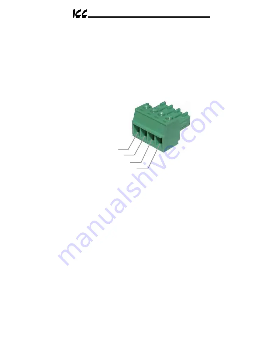
Figure 5 indicates the specific network connections to the RS-485 pluggable
terminal block (CN3). In general, there is no universal standardized labeling
scheme for RS-485 signal connections, so other equipment on your network
may use labels such as “+” and “-“ or “S1” and “S2”, etc. In such instances,
the correct connection scheme is usually intuitive (e.g. in FLN installations,
connection “+” to “A” and “-“ to “B”), or typically can be obtained via trial and
error by simply swapping the signal wires if no connection can be achieved.
Note that the “Shield” terminal has no internal connection: its purpose is simply
to provide a network cable shield chaining location between devices. The
shield is then typically connected to ground at one location only.
A
B
Signal Ground
Shield
Figure 5: RS-485 Terminal Block (CN3) Connections
Buy: www.ValinOnline.com | Phone 844-385-3099 | Email: [email protected]


