background image

Note: 

If an adapter is already installed in the riser card, the riser card and 

adapter are removed together. 

 6. 

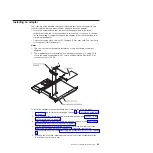
   Carefully grasp the one-slot riser card by its top edge or upper corners, and 

pull the riser card straight up and out of the system-board tray. 

 7. 

   Carefully set the riser card on a flat, static-protective surface. If an adapter is 

installed in the riser card, remove it. 

 8. 

   Touch the static-protective package that contains the adapter that you are 

installing to any unpainted metal surface on the system-board tray; then, 
remove the adapter from the static-protective package. Avoid touching the 
components and gold-edge connectors on the adapter. 

 9. 

   Follow the instructions that come with the adapter to set any jumpers or 

switches. 

10.    Carefully grasp the adapter by the top edge or upper corner and insert it in the 

one-slot riser card. Align the adapter with the riser card connector; then, press 
the adapter firmly into the connector.

Note: 

Make sure that the adapter is inserted correctly. Improper installation of 

an adapter might damage the PCIe riser-card assembly or the adapter. 

11.    Follow the cabling instructions, if any, that come with the adapter. If possible, 

route the adapter cables before you install the adapter. 

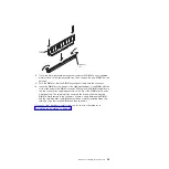
12.    Pinch the two sides of the one-slot riser card, and align the riser card with the 

riser-card connector on the system board; then, press the riser card firmly, 
evenly with both hands, into the connector. 

13.    Install the riser card retaining screw at the front of the system-board tray. 

If you have other devices to install or remove, do so now. Otherwise, go to 
“Completing the installation” on page 30. 


24 

IBM iDataPlex dx360 User's Guide

Содержание System x iDataPlex dx360

Страница 1: ...System x iDataPlex dx360 Types 6313 6316 6385 6390 7831 and 7833 User s Guide...

Страница 2: ......

Страница 3: ...System x iDataPlex dx360 Types 6313 6316 6385 6390 7831 and 7833 User s Guide...

Страница 4: ...n in Appendix B Notices on page 45 and the Warranty and Support Information document on the IBM Documentation CD Fourth Edition June 2011 Copyright IBM Corporation 2011 US Government Users Restricted...

Страница 5: ...talling optional devices 17 Installation guidelines 17 System reliability guidelines 18 Handling static sensitive devices 18 Removing a system board tray from a 2U chassis 19 Removing the system board...

Страница 6: ...gram 48 German Ordinance for Work gloss statement 50 Electronic emission notices 50 Federal Communications Commission FCC statement 50 Industry Canada Class A emission compliance statement 50 Avis de...

Страница 7: ...n tuotteen lue turvaohjeet kohdasta Safety Information Avant d installer ce produit lisez les consignes de s curit Vor der Installation dieses Produkts die Sicherheitshinweise lesen Prima di installar...

Страница 8: ...there is evidence of fire water or structural damage v Disconnect the attached power cords telecommunications systems networks and modems before you open the device covers unless instructed otherwise...

Страница 9: ...es or regulations Statement 3 CAUTION When laser products such as CD ROMs DVD drives fiber optic devices or transmitters are installed note the following v Do not remove the covers Removing the covers...

Страница 10: ...e ensure that all power cords are disconnected from the power source 1 2 Statement 8 CAUTION Never remove the cover on a power supply or any part that has the following label attached Hazardous voltag...

Страница 11: ...Statement 10 CAUTION Do not place any object on top of rack mounted devices Safety ix...

Страница 12: ...x IBM iDataPlex dx360 User s Guide...

Страница 13: ...ou ordered you received one or more of the following server solutions v Two dx360 system board trays installed in a 2U chassis v One dx360 system board tray and one storage enclosure installed in a 2U...

Страница 14: ...and danger statement that appears in the documentation has a number that you can use to locate the corresponding statement in your language in the Safety Information document v Problem Determination a...

Страница 15: ...in your server and displays the documents in the language for that region if available If a document is not available in the language for that region the English language version is displayed Use one...

Страница 16: ...ch statement is numbered for reference to the corresponding statement in your language in the Safety Information document The following notices and statements are used in this document v Note These no...

Страница 17: ...sk drives or up to five 3 5 inch simple swap SATA hard disk drives PCI expansion slots v Each system board tray supports one PCIe expansion slot Integrated functions v Intel baseboard management contr...

Страница 18: ...drive health The diagnostic programs create a merged log that includes events from all collected logs The information is collected into a file that you can send to IBM service and support Additionally...

Страница 19: ...as the following RAS features v Advanced Configuration and Power Interface ACPI v Advanced Desktop Management Interface DMI features v Automatic error retry or recovery v Automatic memory downsizing o...

Страница 20: ...updates You can download the UpdateXpress program from the Web at no additional cost or you can purchase it on a CD To download the program or purchase the CD go to http www ibm com systems managemen...

Страница 21: ...ver controls and light emitting diodes LEDs and how to turn the system board tray on and off System board tray components The following illustration shows the major components in the dx360 system boar...

Страница 22: ...system board that are used for installing options See Operator panel controls LEDs connectors and power on page 13 for information about the external connectors See the Problem Determination and Servi...

Страница 23: ...hows the locations of the jumpers on the system board that relate to selected system functions See the Problem Determination and Service Guide for more information about using switches and jumpers on...

Страница 24: ...illustrations in this document might differ slightly from your hardware Fan assembly cover Fan assembly 2U chassis Power supply Hardware configuration examples The iDataPlex 2U flex chassis supports t...

Страница 25: ...for the system board tray for a total of five Depending on the server configuration you can configure the 2U storage server with up to four 3 5 inch simple swap SAS hard disk drives or up to five 3 5...

Страница 26: ...ectors to connect the server to a network Systems management port Connect a systems management device to this serial connector Locator LED This LED can be lit remotely by the system administrator to a...

Страница 27: ...or Connect the power cord to this connector When the chassis is installed in an iDataPlex rack it is connected automatically to power through a power cord that is mounted to the rack rail Chapter 2 Co...

Страница 28: ...e operating system before you turn off the system board tray See the operating system documentation for information about shutting down the operating system The system board tray can be turned off in...

Страница 29: ...te the weight of the object equally between your feet Use a slow lifting force Never move suddenly or twist when you lift a heavy object To avoid straining the muscles in your back lift by standing or...

Страница 30: ...ectricity to build up around you v The use of a grounding system is recommended For example wear an electrostatic discharge wrist strap if one is available v Handle the device carefully holding it by...

Страница 31: ...he chassis they can be removed independently of each other 2 If a storage enclosure is installed on the system board tray you will remove the storage enclosure and the system board tray from the chass...

Страница 32: ...and all attached devices see Turning off the system board tray on page 16 3 If the system board tray is installed in a chassis remove it see Removing a system board tray from a 2U chassis on page 19...

Страница 33: ...see Removing a system board tray from a 2U chassis on page 19 4 Carefully set the system board tray on a flat static protective surface 5 Note the cable routing and connection locations then disconne...

Страница 34: ...ion guidelines on page 17 2 Turn off the system board tray and all attached devices see Turning off the system board tray on page 16 3 Remove the filler panel from the simple swap hard disk drive bay...

Страница 35: ...ages for a single PCIe slot is the same as specified in PCI Local Bus Specification Revision 2 3 for conventional slots 25 W To install an adapter in the system board tray complete the following steps...

Страница 36: ...witches 10 Carefully grasp the adapter by the top edge or upper corner and insert it in the one slot riser card Align the adapter with the riser card connector then press the adapter firmly into the c...

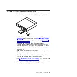
Страница 37: ...n the outside of the system board tray for at least 2 seconds then remove the hard disk drive from the package Attention Do not press on the top of the drive Pressing the top might damage the drive 5...

Страница 38: ...mory depends on the system configuration Some memory is reserved for system resources To view the total amount of installed memory and the amount of configured memory run the Configuration Setup Utili...

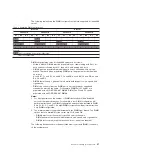
Страница 39: ...ct to size speed and organization v DIMM size can vary from one DIMM pair to another however speed and organization must be the same For example DIMM Pair A1 and B1 are populated with x8 1GB DDR2 667...

Страница 40: ...it see Removing a system board tray from a 2U chassis on page 19 5 If a storage enclosure is installed on the system board tray remove it see Removing a storage enclosure on page 21 Otherwise remove...

Страница 41: ...ector Firmly press the DIMM straight down into the connector by applying pressure on the top of the DIMM at both ends simultaneously The retaining clips snap into the locked position when the DIMM is...

Страница 42: ...stem board tray into the chassis until the cover is installed and closed or a storage enclosure is installed Do not attempt to override this protection Note If a storage enclosure is installed on the...

Страница 43: ...ins at the rear slide down into the slots at the rear of the system board tray Before you close the storage enclosure make sure that all components are installed and seated correctly all internal cabl...

Страница 44: ...andles click into place 3 Reconnect the cables on the front of the system board tray 4 Turn on the system board tray see Turning on the system board tray on page 16 5 Make sure that the power on LED o...

Страница 45: ...documentation that comes with each device If the server has an optional RAID adapter and you have installed or removed a hard disk drive see the documentation that comes with the RAID adapter for info...

Страница 46: ...34 IBM iDataPlex dx360 User s Guide...

Страница 47: ...n page 38 v Gigabit Ethernet controller configuration To configure the integrated Gigabit Ethernet controller see Configuring the Gigabit Ethernet controller on page 38 v IBM Dynamic System Analysis D...

Страница 48: ...and Service Guide 3 Select settings to view or change BIOS Setup Utility menu choices Note Some options in the BIOS configuration menus might not be supported in all server configurations The followin...

Страница 49: ...the System Information v Boot Options Select this choice to view boot devices during POST or to change the order in which you want to boot the devices v Boot Manager Select this choice to view a list...

Страница 50: ...e system board tray 2 Restart the system board tray 3 Press F2 4 Select Boot Manager 5 Select the startup device and press Enter to boot from the selected device The next time the system board tray is...

Страница 51: ...ing the instructions that are included with the downloaded files When you replace a device in the server you might have to either update the server with the latest version of the firmware that is stor...

Страница 52: ...l session with the Red Hat operating system 4 Type the following commands to display the entire set of IP parameters for the baseboard management controller v modprobe ipmi_si and press Enter v modpro...

Страница 53: ...ddress is set by dynamic host controller protocol DHCP or is set statically by the user 7 To change the baseboard management controller IP address for SUSE Linux type ipmitool lan set 1 ipscr static a...

Страница 54: ...42 IBM iDataPlex dx360 User s Guide...

Страница 55: ...our IBM product The documentation that comes with IBM systems also describes the diagnostic tests that you can perform Most systems operating systems and programs come with documentation that contains...

Страница 56: ...M services see http www ibm com services or see http www ibm com planetwide for support telephone numbers In the U S and Canada call 1 800 IBM SERV 1 800 426 7378 Hardware service and support You can...

Страница 57: ...INCLUDING BUT NOT LIMITED TO THE IMPLIED WARRANTIES OF NON INFRINGEMENT MERCHANTABILITY OR FITNESS FOR A PARTICULAR PURPOSE Some states do not allow disclaimer of express or implied warranties in cert...

Страница 58: ...he United States other countries or both Red Hat the Red Hat Shadow Man logo and all Red Hat based trademarks and logos are trademarks or registered trademarks of Red Hat Inc in the United States and...

Страница 59: ...ger needed IBM offers a variety of product return programs and services in several countries to assist equipment owners in recycling their IT products Information on IBM product recycling offerings ca...

Страница 60: ...vailable to customers for the return recycling and recovery of WEEE Customer participation is important to minimize any potential effects of EEE on the environment and human health due to the potentia...

Страница 61: ...rebut mais plut t r cup r e en fin de cycle de vie selon cette norme In accordance with the European Directive 2006 66 EC batteries and accumulators are labeled to indicate that they are to be collec...

Страница 62: ...rdance with the instruction manual may cause harmful interference to radio communications Operation of this equipment in a residential area is likely to cause harmful interference in which case the us...

Страница 63: ...including the fitting of non IBM option cards This product has been tested and found to comply with the limits for Class A Information Technology Equipment according to CISPR 22 European Standard EN...

Страница 64: ...Japanese Voluntary Control Council for Interference VCCI statement Korean Class A warning statement 52 IBM iDataPlex dx360 User s Guide...

Страница 65: ...environment 5 Ethernet integrated on system board 38 Ethernet connector 14 Ethernet controller configuring 38 Ethernet controller configuration 35 Ethernet transmit receive activity LED 14 expansion...

Страница 66: ...ystem board tray 16 statements and notices 4 stopping the system board tray 16 storage enclosure installing 31 removing 21 support web site 43 symmetric multiprocessing 7 system board components 9 sys...

Страница 67: ......

Страница 68: ...Part Number 90Y5678 Printed in USA 1P P N 90Y5678...

Отзывы: