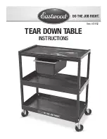
▌1▐
Inner connector on upper CMA
▌2▐
Connector base on inner rail member
▌3▐
Outer connector on upper CMA
▌4▐
Connector base on outer rail member
▌5▐
Support rail connector on upper CMA
▌6▐
Connector base on outer rail member
2.
Install the inner connector of the upper CMA assembly (
▌1▐
) to the inner
member of the left support rail (
▌2▐
), as shown in Figure 54 from the outer and
inner support rails.
3.
Install the inner connector of the upper CMA assembly (
▌3▐
) to the inner
member of the left support rail (
▌4▐
), as shown in Figure 55 on page 66.
svc01035
1
2
3
4
5
6
Figure 53. Connectors for the cable management arm
1
4
2
svc01036
Figure 54. Install the inner connector of the upper CMA to the inner member of the support rail
Chapter 2. Installing the Storwize V7000 Gen2 and Storwize V7000 Gen2+ hardware
65
Содержание StorVize V7000 Gen2
Страница 8: ...viii Storwize V7000 Gen2 and Gen2 Quick Installation Guide ...
Страница 24: ...xxiv Storwize V7000 Gen2 and Gen2 Quick Installation Guide ...
Страница 36: ...12 Storwize V7000 Gen2 and Gen2 Quick Installation Guide ...
Страница 166: ...142 Storwize V7000 Gen2 and Gen2 Quick Installation Guide ...
Страница 174: ...150 Storwize V7000 Gen2 and Gen2 Quick Installation Guide ...
Страница 176: ...152 Storwize V7000 Gen2 and Gen2 Quick Installation Guide ...
Страница 184: ...160 Storwize V7000 Gen2 and Gen2 Quick Installation Guide ...
Страница 187: ......
Страница 188: ...IBM Printed in USA GC27 6500 08 ...