


3.
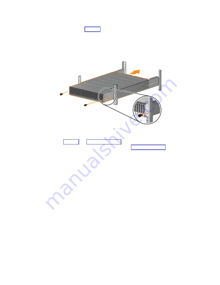
Slide the enclosure into the rack along the rails until the enclosure is fully
inserted (see Figure 19).
Note:
The rails are not designed to hold an enclosure that is partially inserted.
The enclosure must always be in a fully inserted position. Control enclosures
must be installed only on the supplied control enclosure rails. Expansion
enclosures must be installed only on the supplied expansion enclosure rails.
4.
Secure the enclosure with screws in the rack mounting screw holes. (See
Figure 19 and Figure 20 on page 23.)
5.
Reinstall the left and right end caps. (See Figure 20 on page 23.) The left end
cap has indicator windows that align with the status LEDs (light-emitting
diodes) on the edge of the enclosure.
a.
Ensure that the serial number of the end cap matches the serial number on
the rear of the enclosure.
b.
Fit the slot on the top of the end cap over the tab on the chassis flange.
c.
Rotate the end cap down until it snaps into place.
d.
Ensure that the inside surface of the end cap is flush with the chassis.
1
2
fab10021
Figure 19. Inserting the enclosure
22
Storwize V7000 Gen2 and Gen2+: Quick Installation Guide
Содержание StorVize V7000 Gen2
Страница 8: ...viii Storwize V7000 Gen2 and Gen2 Quick Installation Guide ...
Страница 24: ...xxiv Storwize V7000 Gen2 and Gen2 Quick Installation Guide ...
Страница 36: ...12 Storwize V7000 Gen2 and Gen2 Quick Installation Guide ...
Страница 166: ...142 Storwize V7000 Gen2 and Gen2 Quick Installation Guide ...
Страница 174: ...150 Storwize V7000 Gen2 and Gen2 Quick Installation Guide ...
Страница 176: ...152 Storwize V7000 Gen2 and Gen2 Quick Installation Guide ...
Страница 184: ...160 Storwize V7000 Gen2 and Gen2 Quick Installation Guide ...
Страница 187: ......
Страница 188: ...IBM Printed in USA GC27 6500 08 ...


