4.
If needed, repeat steps 2 on page 90 and 3 on page 91 to replace the other FIB.
5.
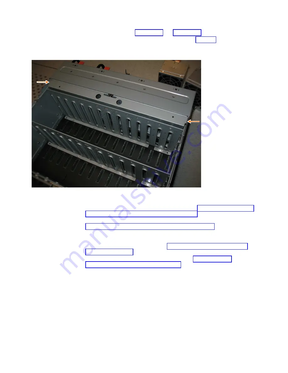
Replace the narrow metal cover, which is shown in Figure 86, over the FIB
assemblies. The attachment screws are on each side of the chassis.
6.
Place the enclosure back in the rack, as described in “Installing or replacing an
expansion enclosure in a rack: 2076-92F” on page 49
7.
Replace each of the fan modules. Follow the procedure that is described in
“Installing or replacing a fan module: 2076-92F” on page 88.
8.
Replace the drives, secondary expander modules, and other heavy FRUs that
were removed before the enclosure was removed from the rack.
9.
Replace the top cover, as described in “Installing or replacing the top cover:
2076-92F” on page 68.
10.
Reconnect power to the enclosure, as described in “Powering on the
expansion enclosure: 2076-92F” on page 127.
Removing an expansion enclosure from a rack: 2076-92F
You might need to slide the 2076-92F expansion enclosure out of the rack to apply
service. For some tasks, you might need to completely remove the expansion
enclosure from the rack.
svc01069
Figure 86. Replace the FIB cover
92
Storwize V7000 Gen2 and Gen2+: Quick Installation Guide
Содержание StorVize V7000 Gen2
Страница 8: ...viii Storwize V7000 Gen2 and Gen2 Quick Installation Guide ...
Страница 24: ...xxiv Storwize V7000 Gen2 and Gen2 Quick Installation Guide ...
Страница 36: ...12 Storwize V7000 Gen2 and Gen2 Quick Installation Guide ...
Страница 166: ...142 Storwize V7000 Gen2 and Gen2 Quick Installation Guide ...
Страница 174: ...150 Storwize V7000 Gen2 and Gen2 Quick Installation Guide ...
Страница 176: ...152 Storwize V7000 Gen2 and Gen2 Quick Installation Guide ...
Страница 184: ...160 Storwize V7000 Gen2 and Gen2 Quick Installation Guide ...
Страница 187: ......
Страница 188: ...IBM Printed in USA GC27 6500 08 ...


