7
Cables
v
16
RS232
cables
for
each
HMC.
One
cable
from
each
HMC
to
each
processor
subsystems.
A
maximum
of
32
RS232
cables
per
rack
is
possible.
v
Two
RS422
cables
for
each
HMC.
Two
RS422
cables
from
each
HMC
attach
to
each
Bulk
Power
Controller
(BPC).
A
maximum
of
four
RS422
cables
per
rack.
It
is
recommended
that
an
Ethernet
network
be
connected
to
the
system.
Each
HMC
can
connect
to
each
partition
running
on
a
processor
subsystem
to
enable
implementation
of
the
service
functions
that
are
available.
The
Ethernet
network
is
used
for
Service
Focal
Point
(see
the
IBM
Hardware
Management
Console
for
pSeries
Installation
and
Operations
Guide
for
detailed
information).
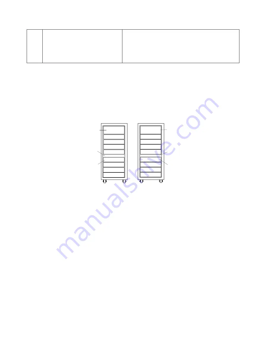
Redundant
Integrated
Battery
Feature
(IBF)
For
a
redundant
IBF,
both
the
IBF
A
and
B
must
be
installed.
IBF
A
is
installed
in
the
front
of
the
rack.
IBF
B
is
installed
in
the
rear
of
the
rack.
The
IBFs
attach
to
the
corresponding
bulk
power
regulators
(BPRs)
at
the
top
of
the
rack.
See
the
following
illustration:
Front
Rear
BPR A1
BPR A2
BPR A3
IBF A2
IBF A1
IBF A3
BPR B1
BPR B2
BPR B3
IBF B2
IBF B1
IBF B3
Nonredundant
Integrated
Battery
Feature
(IBF)
For
a
nonredundant
IBF,
only
IBF
A
is
installed
in
the
front
of
the
rack.
See
the
previous
illustration.
Maximum
I/O
Subsystem
and
Processor
Subsystem
Configuration
A
maximum
I/O
drawer
configuration
consists
of
five
I/O
subsystems
and
five
or
six
processor
subsystems.
To
get
to
the
maximum
configuration
of
five
I/O
subsystems,
the
IBF
feature
cannot
be
used.
The
drawer
position
designated
for
the
first
and
second
IBFs
may
be
used
for
a
fifth
I/O
subsystem;
therefore,
the
first
and
second
IBFs
cannot
be
installed.
The
drawer
locations
for
the
fifth
I/O
subsystem,
or
two
or
four
IBFs,
are
U1.13
and
U1.15.
The
five
I/O
subsystem
configuration
results
in
the
third
IBF
never
being
installed,
because
the
first
and
second
IBFs
are
not
installed.
128
Eserver
pSeries
655
Installation
Guide
Содержание pseries 655
Страница 1: ...pSeries 655 Installation Guide SA38 0616 03 ERserver...
Страница 2: ......
Страница 3: ...pSeries 655 Installation Guide SA38 0616 03 ERserver...
Страница 14: ...xii Eserver pSeries 655 Installation Guide...
Страница 22: ...6 Eserver pSeries 655 Installation Guide...
Страница 54: ...38 Eserver pSeries 655 Installation Guide...
Страница 101: ...2 1 1 Top of Cassette 2 Handle Chapter 4 Installation and Removal Procedures 85...
Страница 125: ...1 Metal EMC Shield 2 Adapter Bracket Chapter 4 Installation and Removal Procedures 109...
Страница 128: ...112 Eserver pSeries 655 Installation Guide...
Страница 132: ...116 Eserver pSeries 655 Installation Guide...
Страница 156: ...140 Eserver pSeries 655 Installation Guide...
Страница 204: ...188 Eserver pSeries 655 Installation Guide...
Страница 211: ......
Страница 212: ...Part Number 80P3836 Printed in USA February 2004 SA38 0616 03 1P P N 80P3836...


