manualshive.com logo in svg
background image

When you connect SCSI drives to the SCSI adapter, start with the
SCSI connector on the cable that is farthest from the adapter.
Then, with each additional device, work your way in from the far
end back towards the adapter. Connecting the devices in this
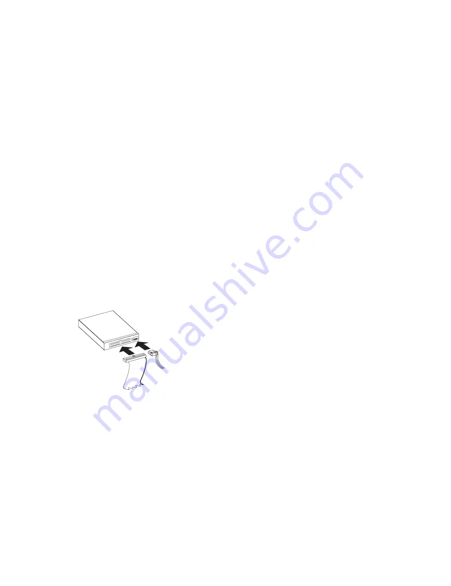
order ensures the best possible signal quality. Connect the SCSI
and power cables to the tape drive connectors. Ensure that pin 1
of the SCSI cable aligns with pin 1 of the SCSI connector. Pin 1
is usually a different color than the other pins so that it can be
easily identified. If your SCSI cable is a different size than the
connector on your tape drive, use the converter that is included in
the option package. For more information, see “Step 5.
Connecting Cables and Terminating the Chain” on page 2-6.

8. If the tape drive is the last device on the SCSI chain, the chain

must be terminated at the drive. To terminate the SCSI chain,
you must set the Active Termination Enabled jumper to ON. To
locate the Active Termination Enabled jumper, refer to the
illustration on page 1-2. There is also an illustration on page 1-2
which shows how to set jumpers to ON or OFF.

9. Replace the computer cover and secure it in place. Reconnect the

power cord and any other signal cables. Turn on all attached
devices; then turn on the computer. Ensure that the appropriate
advanced SCSI programming interface (ASPI) device drivers are
installed to support the tape drive. These device drivers are
usually provided with the SCSI adapter. You might need to
reconfigure your SCSI adapter. See the documentation that
comes with your computer or adapter.

10. After the power is turned on, or after any power reset, the tape

drive performs a power-on self test. This is indicated by both
LEDs blinking for about 5 seconds. It is important to make sure
the drive is empty during the self-test. Do not try to insert a
cartridge into the tape drive during the self-test.

11. Install your backup and restore software. Follow the installation

and operating instructions included with your software to begin
using the tape drive. For more information, see “Backup and
Restore Server Software” on page 2-2.

12. If your computer does not recognize your tape drive during the

computer’s power-on self test (POST) or if you receive startup
errors, run the configuration-setup utility program as described in
the documentation that comes with your computer.

1-4    12/24 GB DDS/3 4 mm Internal Tape Drive

All manuals and user guides at all-guides.com

Содержание OPTIONS 12/24 GB

Страница 1: ...12 24 GB DDS 3 4mm Internal Tape Drive User s Guide OPTIONS by IBM All manuals and user guides at all guides com a l l g u i d e s c o m...

Страница 2: ...u This publication could include technical inaccuracies or typographical errors Changes are periodically made to the information herein these changes will be incorporated in new editions of the public...

Страница 3: ...Mounting the Drive 2 5 Step 5 Connecting Cables and Terminating the Chain 2 6 Step 6 Completing the Installation 2 7 Step 7 Updating the Configuration 2 7 Step 8 Installing Backup and Restore Softwar...

Страница 4: ...mation 3 13 Step 1 Troubleshooting 3 13 Step 2 Preparing for the Call 3 14 Step 3 Placing the Call to IBM 3 14 Appendix E Product Warranty 3 15 Appendix F Notices and Trademarks 3 17 iv 12 24 GB DDS 3...

Страница 5: ...ins Product description Detailed installation instructions Detailed usage information Part 3 contains Safety information Product specifications Help and Service information Warranty Notices and tradem...

Страница 6: ...an overview of the installation instructions For more detailed information and a list of tested server backup and restore software see Backup and Restore Server Software on page 2 2 CAUTION Read the S...

Страница 7: ...not touch any exposed components on the drive To install the drive refer to the following drive backpanel illustration 1 SCSI connection 2 Jumper block 3 Power connection 4 Use the jumper block 2 to s...

Страница 8: ...rtical position The drive has two sets of mounting holes to allow for a number Pins 5 6 Pins 3 4 Pins 1 2 SCSI ID of mounting positions There are two holes 1 2 in each set use only one set of mounting...

Страница 9: ...e the computer cover and secure it in place Reconnect the power cord and any other signal cables Turn on all attached devices then turn on the computer Ensure that the appropriate advanced SCSI progra...

Страница 10: ...warranty in Appendix E or contact your IBM reseller For writing data use only IBM 59H3465 data cartridges For more information on compatible cartridges see Appendix B On the back of the data cartridge...

Страница 11: ...data cartridge One cleaning cartridge Four M3 x 0 5 x 6 mm mounting screws One SCSI converter for attaching a 50 pin device to a 68 pin cable One 3 5 inch bezel Before You Begin To install this drive...

Страница 12: ...5 0 for SCO Software for Windows NT Cheyenne ARCserve v 6 0 for Windows NT Seagate Backup Exec v 6 0 Rev 90 for Windows NT Microsoft NT 3 51 native tape support Microsoft NT 4 0 native tape support S...

Страница 13: ...drives Assign the tape drive to the lowest available SCSI ID Depending on your computer there are several ways to view your current SCSI ID setting For most IBM computers press F1 during the startup a...

Страница 14: ...to the following illustrations Remove and position jumpers to obtain the ID If necessary use a pair of flat nose pliers to remove the jumpers The following illustration shows the ON and OFF positions...

Страница 15: ...tions Use one of the two sets of mounting holes that provides the best fit and mounts the drives securely The illustration shows the pairs of hole on only one side of the drive 3 Align the drive bay s...

Страница 16: ...a different color than the other pins to make it easier to identify 3 The following example shows a bus cable with two devices on it The last device 1 on a bus cable must terminate the device chain 1...

Страница 17: ...guration For many computers the power on self test POST and the configuration setup utility program automatically recognize the new tape drive However you might have to answer questions about your sys...

Страница 18: ...ape drive needs cleaning or that the cartridge needs to be replaced Right amber This light indicates drive status When this light is on the tape drive is reading or writing to tape When this light is...

Страница 19: ...ration LED Action Meaning Amber On The tape drive is reading or writing to tape Amber Flashing rapidly A hardware fault occurred Green On A cartridge is inserted and does not generate errors Green Fla...

Страница 20: ...ible after the indicator light turns on Clean the tape drive more often if you are using a lot of new tapes or if you are operating in an environment which contains a lot of dust or other particulate...

Страница 21: ...roduct Specifications This appendix includes the following specifications and requirements Typical Data Capacity Power Specifications Typical Data Transfer Rates Environmental Specifications SCSI Cabl...

Страница 22: ...lliamps 800 milliamps Maximum Wet Bulb Temperature 78 8 F 26 C maximum No condensation Ripple Peak to Peak 100 mv 100 mv Altitude 100 m to 4575 m 330 ft to 15000 ft 300 m to 15200 m 985 ft to 49900 ft...

Страница 23: ...mming Interface ASPI device drivers are installed to support the tape drive Device drivers usually are provided with the SCSI host adapter Tape operation is unreliable Clean the tape heads Try another...

Страница 24: ...u through the problem during the call Step 3 Placing the Call to IBM Technical support is available during the warranty period to answer any questions about your new IBM option Support response time w...

Страница 25: ...ate of Installation unless IBM or your reseller informs you otherwise During the warranty period IBM or your reseller if authorized by IBM will provide warranty service under the type of service desig...

Страница 26: ...or 2 in transit in those cases where IBM is responsible for the transportation charges Extent of Warranty IBM does not warrant uninterrupted or error free operation of a Machine The warranties may be...

Страница 27: ...able in all countries in which IBM operates Any reference to an IBM product program or service is not intended to state or imply that only that IBM product program or service may be used Subject to IB...

Страница 28: ...Microsoft Windows Windows NT and the Windows 95 logo are trademarks or registered trademarks of Microsoft Corporation Other company product or service names may be trademarks or service marks of other...

Страница 29: ...All manuals and user guides at all guides com...

Страница 30: ...IBM Part Number 4305342 Printed in U S A 43 5342 All manuals and user guides at all guides com...

Отзывы: