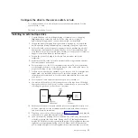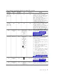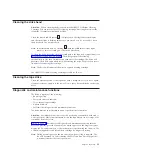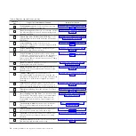
remainder of the power-on and initialization phase. The status LED becomes
solid green after the power-on/initialization and POST are complete.
6.
Turn off the enclosure.
7.
Disconnect the power cord from both the enclosure and the electrical outlet.
Connect the internal cable
Connect the enclosure internal SAS cable to the SAS connector on the drive. Attach
the host side (data and power) of the SAS cable included with your tape drive to
the SAS and power connectors on your server. Then, attach the drive side to the
drive connector (for the drive connector location, see “Rear panel of the drive” on
page 3.
Run drive diagnostics
1.
Replace the cover on the enclosure.
2.
If you are not already connected to a power source, connect the power cord to
both the enclosure and the electrical outlet.
3.
Turn on the enclosure.
4.
Run one or more of the following drive diagnostics:
v
“Function code 1: Run drive diagnostics” on page 26
v
“Function code 6: Run host interface wrap test” on page 30
v
“Function code 7: Run RS-422 wrap test” on page 31
If an error code appears on the single-character display (SCD), go to
Appendix C, “Error codes and messages,” on page 59. If no error appears,
continue to the next step.
5.
Turn off the enclosure.
6.
Disconnect the power cord from both the enclosure and the electrical outlet.
Install device drivers
If you intend to use the tape drive with a commercial software application, see the
documentation for that application to install the device driver and configure the
tape drive.
Connect the external interface cable (tape enclosure
installations only)
For information about connecting the enclosure, see the documentation for your
enclosure.
Connect the external SAS interface to the server
To connect the enclosure to the SAS interface, complete the following steps:
1.
Connect the external SAS cable that ships with the drive to both the enclosure
and the server (for the location of the connectors, refer to the documentation
for your enclosure and server).
2.
Run the applicable SAS attachment verification procedure for your server.
If you want to power a device on or off while it is connected to the same bus as a
drive, you can do so if, during the power-on cycle, you quiesce all devices
(including the drive) on the bus.
14
Half-High LTO Gen 5 SAS Tape Drive Installation and User's Guide
Содержание L5X
Страница 2: ......
Страница 10: ...viii Half High LTO Gen 5 SAS Tape Drive Installation and User s Guide...
Страница 14: ...xii Half High LTO Gen 5 SAS Tape Drive Installation and User s Guide...
Страница 16: ...xiv Half High LTO Gen 5 SAS Tape Drive Installation and User s Guide...
Страница 58: ...40 Half High LTO Gen 5 SAS Tape Drive Installation and User s Guide...
Страница 71: ...Figure 14 RID tag on rear panel Chapter 5 Resolving problems 53...
Страница 72: ...54 Half High LTO Gen 5 SAS Tape Drive Installation and User s Guide...
Страница 76: ...58 Half High LTO Gen 5 SAS Tape Drive Installation and User s Guide...
Страница 90: ...72 Half High LTO Gen 5 SAS Tape Drive Installation and User s Guide...
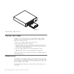
Страница 94: ...Figure 26 Sliding the drive forward 76 Half High LTO Gen 5 SAS Tape Drive Installation and User s Guide...
Страница 102: ...84 Half High LTO Gen 5 SAS Tape Drive Installation and User s Guide...
Страница 119: ......
Страница 120: ...Part Number 60Y1487 Printed in USA 1P P N 60Y1487...


