background image

481

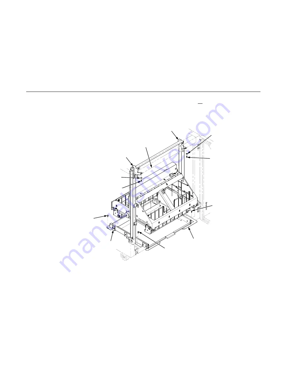
24. Install finger tight the 10-32 x 5/32 inch buttonhead screw and washer securing the left vertical rail to the upper frame 

cross-member. (Do not install the right hand screw yet.) (Figure 78.)

25. Install and tighten the two Torx T-10 screws securing the stacker base to the cabinet floor. (Figure 78.)

26. Install and tighten the two Torx T-10 screws that secure the rail bracket to the cabinet floor. (Figure 78.)

Figure 78. This figure shows which screws to install to secure the stacker assembly in the rear of the cabinet.

Washer

Right Screw, 10-32 x 5/32 inch

Stacker Base

Screw, Torx T-10

Right Vertical Rail

Upper Frame 
Cross-Member

Rail Bracket

Screw, 
Torx T-10 
(2 places)

Screw, 
Torx T-10

Washer

Left Screw, 10-32 x 5/32 inch

Left Vertical Rail

Содержание Infoprint 6500-v05

Страница 1: ...Infoprint 6500 Line Matrix Printers Models 6500 v05 v5P v10 v1P v15 and v20 Maintenance Information Manual Form No G544 5978 00...

Страница 2: ...ality Publications are not stocked at the address given below You may send your comments by facsimile to 1 800 524 1519 by E mail to printpub us ibm com or by mail to IBM Printing Systems Division Inf...

Страница 3: ...ation 21 Prepare The Printer For Inspection 21 Inspect Mechanical Parts 22 Inspect Electrical Parts 23 Preface 26 About This Manual 26 Printing Conventions In This Manual 27 Related Documents 28 About...

Страница 4: ...Contents 212 Operator Print Tests 213 Selecting And Running Tests 215 Customer Engineer CE Tests 216 Boot Diagnostics Menu 221 Hex Code Printout 224 Printer Information Menu 226 Soft vs Hard Reset 22...

Страница 5: ...62 Locations Of Components And Assemblies 262 4 Circuit Diagrams Circuit Boards Cables and Switches 264 Contents 264 5 Removals and Adjustments 311 About This Chapter 311 Tools And Materials 311 Prepa...

Страница 6: ...er Feed 342 Motor Assembly Platen Open 344 Motor Assembly Ribbon Drive 346 Operator Panel Assembly 347 Paper Guide Assembly 348 Paper Ironer 349 Platen 350 Platen Stop Assembly 354 Resistors Terminati...

Страница 7: ...6 Parts Catalog 390 Organization Of This Chapter 390 Illustrated Parts Breakdown 390 7 Preventive Maintenance 431 Contents 431 Cleaning The Printer 432 Cleaning The Exterior 432 Cleaning The Interior...

Страница 8: ...Constant Force Spring 485 Replacing The Timing Belts 487 Replacing The Roller Drive Shaft 491 Illustrated Parts Breakdown 494 List of Illustrations 494 F Printer Specifications 504 Contents 504 Ribbon...

Страница 9: ...Table of Contents 9 Cables 511 Printing Rates 512 G Metric Conversion Tables 515 Length 515 Torque and Force 516 Mass and Density 516 Temperature 517 Power 517 H Torque Table 518 I Abbreviations 520...

Страница 10: ...for products and services offered in the U S A IBM may not offer the products services or features discussed in this document in other countries Consult your IBM representative for information on the...

Страница 11: ...Therefore the results obtained in other operating environments may vary significantly Some measurements may have been made on development level systems and there is no guarantee that these measuremen...

Страница 12: ...e harmful interference to radio communications Operation of this equipment in a residential area is likely to cause harmful interference in which case the user will be required to correct the interfer...

Страница 13: ...Such cables and connectors are available from IBM authorized dealers IBM cannot accept responsibility for any interference caused by using other than recommended cables and connectors Industry Canada...

Страница 14: ...nvironment this product may cause radio interference in which case the user will be required to take adequate measures Australia New Zealand Attention This is a Class A Product In a domestic enviromen...

Страница 15: ...Klasse A Text f r alle in Deutschland vertriebenen EN 55022 Klasse A Ger te Zulassungsbescheinigung laut dem Deutschen Gesetz ber die elektromagnetische Vertr glichket von Ger ten EMVG vom 18 Septembe...

Страница 16: ...modification of the product including the fitting of non IBM option cards Dieses Ger t ist berechtigt in bereinstimmung mit dem deutschen EMVG vom 9 Nov 92 das EG Konformit tszeichen zu furhren Prope...

Страница 17: ...erates under conditions of high electrical potentials and heat generation both of which are functionally necessary Lightning Safety To avoid personal risk do not install or reconfigure a communication...

Страница 18: ...mportant indicates information vital to proper operation of the printer NOTE A note gives you helpful information and tips about printer operation and maintenance This symbol indicates a part or assem...

Страница 19: ...companies and are designated by two asterisks in this manual Acrobat Adobe Systems Incorporated Adobe Adobe Systems Incorporated Auto Label Mapping Printronix Inc Centronics Genicom Corporation Code...

Страница 20: ...ustrial Programming Inc PGL Printronix Inc PKZIP PKWARE Inc Printronix Printronix Inc PSA3 Printronix Inc QMS Quality Micro Systems Inc RibbonMinder Printronix Inc SureStak Printronix Inc Torx Camcar...

Страница 21: ...Inspection Have the following items available Electrical Safety for IBM Customer Engineers Order No S229 8124 A Fluke meter P N 8496278 or similar device for measuring electrical resistance and voltag...

Страница 22: ...e not loose or damaged Make sure they touch the contact strips on the frame when the cover is closed g Close the top cover Make sure the operator panel is centered in the opening of the cover 2 On cab...

Страница 23: ...are summarized in and Figure 2 Figure 1 This figure is a detail drawing showing the ground lug for the circuit breaker of cabinet models 4 Set a Fluke meter P N 8496278 or similar device to the lowes...

Страница 24: ...inter AC Power On Off Switch 5V Remote 5V 48V 5V 5V 48V 48V 24V 48V 8 5 48V 8 5V 5V 5V 48V 48V 5V Primary Earth Ground P101 1 2 3 4 5 6 7 8 9 10 11 12 N AC FAIL N STBY 5V 5V 5V RET LOGIC GND 5V RET LO...

Страница 25: ...t operation of the printer This ground must be connected either to the electrical service ground or to a suitable building ground The printer power cable has a green or green yellow insulated groundin...

Страница 26: ...s a field service maintenance manual for IBM Infoprint 6500 line matrix printers Refer to the Table of Contents or the Index to locate the maintenance information you need How To Replace Parts 1 Go to...

Страница 27: ...llowing features in the illustrations Printing Conventions In This Manual Operator panel keys and LCD messages are set off from regular text in this manual Operator panel keys and indicators are print...

Страница 28: ...eference G544 5979 IBM Infoprint 6500Line Matrix Printer CTA Programmer s Reference G544 5982 IBM Infoprint 6500Line Matrix Printer IPDS Programmer s Reference S544 5984 IBM Infoprint 6500Line Matrix...

Страница 29: ...panel or by sending printer control codes in the data stream from the host computer The IBM Infoprint 6500 Printer Family The Infoprint 6500 line matrix printer family consists of pedestal mount and...

Страница 30: ...er Print Speed of Draft Mode Text Enclosure Hammer Bank 6500 v05 500 LPM Floor Cabinet 28 Hammers 6500 v5P 500 LPM Pedestal 28 Hammers 6500 v10 1000 LPM Floor Cabinet 60 Hammers 6500 v1P 1000 LPM Pede...

Страница 31: ...ion level and the MECA ASIC revision level The configuration is included in the configuration printout Figure 4 shows how to interpret the printer s configuration code Figure 4 This figure show how to...

Страница 32: ...els The paper fence is a wireform divider that separates the source paper stack from the printed output stack For improved performance at higher throughputs the guide chains are used with a moveable f...

Страница 33: ...ess the original shuttle frame assembly or platen has been replaced with a new or rebuilt unit or unless you are instructed to do so in a troubleshooting procedure Never bend or tweak hammer springs A...

Страница 34: ...de moves to the previous menu Scroll function ENTER Selects the option displayed on the LCD This action either sets a value moves to the next lower level of configuration or starts a self test LINE FE...

Страница 35: ...configuration into memory The printer must be in NOT READY mode to do a soft reset RETURN ENTER Toggles the lock on the configuration menus Status Lamp Lit when the printer is in READY mode and the pr...

Страница 36: ...ical Controls Figure 5 36 Figure 5 This figure shows the locations of the electrical controls on floor cabinet and pedestal model printers B A A LCD Power Switch Off On Rotated 180 Degrees A B Status...

Страница 37: ...rms and so on Forms Thickness Lever and Platen Stop The forms thickness lever closes the platen to the relative thickness of the paper The platen stop returns the platen to the lever adjustment set by...

Страница 38: ...ows the locations of the mechanical controls on on floor cabinet and pedestal model printers Paper Supports Tractor Lock Left Tractor Right Tractor Vertical Position Knob Forms Thickness Lever and Sca...

Страница 39: ...it This manual does not cover printer operation or configuration so always have the User s Manual handy when you troubleshoot Troubleshooting At A Glance Start Of Call page 40 How To Troubleshoot pag...

Страница 40: ...inter does not complete IML page 185 Go to No power and operator panel is blank and card cage fan is not running page 184 YES NO Are there black squares on the operator panel NO Go to Printer does not...

Страница 41: ...malfunctioning electronic assembly with an operational spare Most electronic problems are corrected by replacing the printed circuit board assembly sensor or cable that causes the fault indication Th...

Страница 42: ...puter etc A Unit Check condition is a failure detected by self test and fault circuitry Unit check conditions are either recoverable or unrecoverable Recoverable unit check conditions are errors detec...

Страница 43: ...r switch with the optional black back forms switch assembly 4 Power off and unplug the printer Remove the paper guide assembly or pedestal top cover Remove the barrier shield cabinet model or the barr...

Страница 44: ...re replace the controller board page 319 After replacing the controller board DO NOT make the printer READY but proceed immediately to the next step 12 Download and install the latest code from IBM Fi...

Страница 45: ...d platen does not open page 205 5 Check the paper tension between the tractors Adjust the right tractor so that it does not pull paper too tightly or leave it too loose The right tractor should hold t...

Страница 46: ...he failure or message that brought you to this procedure replace the controller board page 319 After replacing the controller board DO NOT make the printer READY but proceed immediately to the next st...

Страница 47: ...he READY state 2 Run the print job that generated the error message If the message appears check the host data for invalid characters 3 Ask the system operator to verify that the printer s Device ID i...

Страница 48: ...e printer If the message appears replace the twinax cable 4 Send a print job to the printer If the message appears go to Communications Failures page 211 014 INVALID ACTIVATE The printer detects a twi...

Страница 49: ...munication with the printer If all other twinax devices work properly and the message still appears replace the coax twinax expansion board Record the message and return it with the defective board 01...

Страница 50: ...ed and not bent or stretched f drive rollers are not damaged Tighten setscrews and replace damaged components as necessary 4 Power off and unplug the printer Remove the paper guide assembly Disconnect...

Страница 51: ...he drive rollers are not damaged g the constant force springs are tightly mounted and undamaged Tighten pulley setscrews and or replace damaged components as necessary 3 Adjust the stacker rails if th...

Страница 52: ...Support 14 If the problem reappears replace the stacker motors 021 BUFFER OVERRUN VERIFY CONFIGURATION The print buffer has overflowed on a serial interface The printed output may contain random aster...

Страница 53: ...e message appears replace the coax twinax multi platform interface Refer to the Coax Twinax Multi Platform Interface Feature Installation and Operation Guide Form Number S246 0149 025 FRAMING ERROR VE...

Страница 54: ...t system 029 8344 DIAGNOSTIC FAILED Link level code test detects a hardware failure on the coax twinax expansion board This message can also occur if the software in flash memory is corrupted 1 Cycle...

Страница 55: ...the paper guide assembly or pedestal top cover Remove the barrier shield cabinet model or the barrier shield and paper guide pedestal model Check that the paper detector switch assembly is securely m...

Страница 56: ...ard DO NOT make the printer READY but proceed immediately to the next step 11 Download and install the latest code from IBM First page 231 12 Power on the printer in download mode and load flash memor...

Страница 57: ...does not move down refer to Reverse paper feed platen does not open page 205 5 Check the paper tension between the tractors Adjust the right tractor so that it does not pull paper too tightly or leave...

Страница 58: ...ading problems go to the appropriate error code for resolution b If you encounter the failure or message that brought you to this procedure replace the controller board page 319 After replacing the co...

Страница 59: ...al Ready and Request to Send Set printer serial interface parameters to match those of the host 2 Send a print job to the printer If the message appears go to Communications Failures page 211 042 NO C...

Страница 60: ...If the problem reappears the controller board or microcode is suspect Do the following 4 Save the printer configuration values Refer to the User s Manual 5 Clear NVRAM page 237 6 Download and install...

Страница 61: ...nd load flash memory page 238 If the message appears replace the flash memory with blank flash containing boot code then load flash memory page 238 4 If the message reappears the controller board or m...

Страница 62: ...Power on the printer in download mode and load flash memory page 238 a If you encounter loading problems go to the appropriate error code for resolution b If you encounter the failure or message that...

Страница 63: ...re Harness Test Tables in Chapter 3 Replace the platen open motor if it fails the resistance test 6 Plug in the printer and power it on Run a print test If the problem reappears the controller board o...

Страница 64: ...ppears power off the printer unplug the printer and go to the next step 5 Remove the shuttle cover Remove the paper guide assembly or the pedestal top cover Inspect the shuttle mechanism for obstructi...

Страница 65: ...3 Download and install the latest code from IBM First page 231 14 Power on the printer in download mode and load flash memory page 238 15 If you encounter the failure after replacing the controller bo...

Страница 66: ...ide assembly or pedestal top cover Check that all fan cables are connected 3 Inspect vents and fan airways for obstructions Look underneath cabinet models for items blocking the cabinet exhaust vents...

Страница 67: ...e the paper guide assembly Disconnect connector P107 from the controller board Test connector P107 EHF for shorts or opens Refer to the Main Wire Harness Test Tables in Chapter 3 Replace components th...

Страница 68: ...cedure replace the controller board page 319 After replacing the controller board DO NOT make the printer READY but proceed immediately to the next step 13 Download and install the latest code from IB...

Страница 69: ...e problem reappears the controller board or microcode is suspect Do the following 8 Save the printer configuration values Refer to the User s Manual 9 Clear NVRAM page 237 10 Download and install the...

Страница 70: ...Display Messages 70 069 DATA CLEARED This message appears when data are cleared out of printer after the CANCEL key has been pressed No action required Table 3 Message List Operator Panel Message Expl...

Страница 71: ...check replace it If it passes the check go to the next step 3 Check the kinds of print jobs the user is running look for very dense graphics and layouts Advise the user to run jobs in smaller batches...

Страница 72: ...ontroller board page 319 After replacing the controller board DO NOT make the printer READY but proceed immediately to the next step 13 Download and install the latest code from IBM First page 231 14...

Страница 73: ...IBM First page 231 7 Power on the printer in download mode and load flash memory page 238 a If you encounter loading problems go to the appropriate error code for resolution b If you encounter the fai...

Страница 74: ...rinter in download mode and load flash memory page 238 a If you encounter loading problems go to the appropriate error code for resolution b If you encounter the failure or message that brought you to...

Страница 75: ...at J106 on the controller board 5 Inspect for obstructions of airways and vents 6 Check the shuttle for electrical shorts page 252 7 Plug in the printer and power it on If the problem reappears the c...

Страница 76: ...se errors as appropriate because they may be the cause of the 084 error 3 Power off and unplug the printer Remove the paper guide assembly or pedestal top cover Before handling circuit boards put on a...

Страница 77: ...er on the printer If the operator panel lights up this indicates PS 5V is working If the CCF runs momentarily about 2 seconds the PS 48V is working and you can go to step 9 d The CCF did not come on i...

Страница 78: ...oulder support Exit this procedure 9 In step 8 you determined that the PS 48V is working therefore an external cable or component connecting to the controller board or the PS is pulling down the PS 48...

Страница 79: ...inter Do NOT put your hands or tools inside the printer when it is plugged in Table 3 Message List Operator Panel Message Explanation Corrective Action DANGER 3 Hazardous voltages are present in the p...

Страница 80: ...V is OK Do P106 wire harness platen motor and other component checks P107 CCF comes on 090 SHUTTLE OPEN 48 V is OK Do P107 wire harness hammer bank fan and other component checks P108 CCF momentarily...

Страница 81: ...propriate procedure in this manual 14 Go to OPERATOR PRINT TESTS in the configuration menu and print a full 136 character width test pattern of All H s If there is any print quality issue go to the ap...

Страница 82: ...38 a If you encounter loading problems go to the appropriate error code for resolution b If you encounter the failure or message that brought you to this procedure replace the controller board page 31...

Страница 83: ...shuttle motor by hand to check that the cables are clear of the shuttle as it moves 6 You can easily verify that when the shuttle cover is installed the hammer bank logic cable is clear of the shuttl...

Страница 84: ...ables 8 Power on the printer If the problem persists check the shuttle for electrical shorts page 252 Replace the shuttle if it is defective 9 Power on the printer If the problem persists refer to the...

Страница 85: ...interlock switch cable from P107 to the switch Replace the platen interlock switch assembly if it fails continuity test 3 Check that the platen interlock switch is not loose 4 Check and adjust the pla...

Страница 86: ...ce the controller board page 319 After replacing the controller board DO NOT make the printer READY but proceed immediately to the next step 12 Download and install the latest code from IBM First page...

Страница 87: ...m IBM First page 231 10 Power on the printer in download mode and load flash memory page 238 a If you encounter loading problems go to the appropriate error code for resolution b If you encounter the...

Страница 88: ...ing problems go to the appropriate error code for resolution b If you encounter the failure or message that brought you to this procedure replace the controller board page 319 After replacing the cont...

Страница 89: ...e appropriate error code for resolution b If you encounter the failure or message that brought you to this procedure replace the controller board page 319 After replacing the controller board DO NOT m...

Страница 90: ...page 237 7 Download and install the latest code from IBM First page 231 8 Power on the printer in download mode and load flash memory page 238 a If you encounter loading problems go to the appropriate...

Страница 91: ...er in download mode and load flash memory page 238 a If you encounter loading problems go to the appropriate error code for resolution b If you encounter the failure or message that brought you to thi...

Страница 92: ...nd load flash memory page 238 a If you encounter loading problems go to the appropriate error code for resolution b If you encounter the failure or message that brought you to this procedure replace t...

Страница 93: ...and load flash memory page 238 a If you encounter loading problems go to the appropriate error code for resolution b If you encounter the failure or message that brought you to this procedure replace...

Страница 94: ...load mode and load flash memory page 238 a If you encounter loading problems go to the appropriate error code for resolution b If you encounter the failure or message that brought you to this procedur...

Страница 95: ...wnload mode and load flash memory page 238 a If you encounter loading problems go to the appropriate error code for resolution b If you encounter the failure or message that brought you to this proced...

Страница 96: ...download mode and load flash memory page 238 a If you encounter loading problems go to the appropriate error code for resolution b If you encounter the failure or message that brought you to this pro...

Страница 97: ...download mode and load flash memory page 238 a If you encounter loading problems go to the appropriate error code for resolution b If you encounter the failure or message that brought you to this pro...

Страница 98: ...he printer in download mode and load flash memory page 238 a If you encounter loading problems go to the appropriate error code for resolution b If you encounter the failure or message that brought yo...

Страница 99: ...and load flash memory page 238 a If you encounter loading problems go to the appropriate error code for resolution b If you encounter the failure or message that brought you to this procedure replace...

Страница 100: ...load mode and load flash memory page 238 a If you encounter loading problems go to the appropriate error code for resolution b If you encounter the failure or message that brought you to this procedur...

Страница 101: ...n download mode and load flash memory page 238 a If you encounter loading problems go to the appropriate error code for resolution b If you encounter the failure or message that brought you to this pr...

Страница 102: ...load mode and load flash memory page 238 a If you encounter loading problems go to the appropriate error code for resolution b If you encounter the failure or message that brought you to this procedur...

Страница 103: ...install the latest code from IBM First page 231 7 Power on the printer in download mode and load flash memory page 238 a If you encounter loading problems go to the appropriate error code for resoluti...

Страница 104: ...ter and power it on If the problem reappears the controller board or microcode is suspect Do the following 6 Save the printer configuration values Refer to the User s Manual 7 Clear NVRAM page 237 8 D...

Страница 105: ...in download mode and load flash memory page 238 a If you encounter loading problems go to the appropriate error code for resolution b If you encounter the failure or message that brought you to this...

Страница 106: ...have good connections Replace as needed Refer to the Cable Shorts Test on page 254 5 Check the shuttle for shorts page 252 6 Plug in the printer and power it on Run the print job again If the message...

Страница 107: ...ilure after replacing the controller board reinstall the original controller board and contact your DDS and Second Level Support 15 Power on the printer Run the print job again If the message appears...

Страница 108: ...code is suspect Do the following 3 Save the printer configuration values Refer to the User s Manual 4 Clear NVRAM page 237 5 Download and install the latest code from IBM First page 231 6 Power on the...

Страница 109: ...nload mode and load flash memory page 238 a If you encounter loading problems go to the appropriate error code for resolution b If you encounter the failure or message that brought you to this procedu...

Страница 110: ...nload mode and load flash memory page 238 a If you encounter loading problems go to the appropriate error code for resolution b If you encounter the failure or message that brought you to this procedu...

Страница 111: ...ownload mode and load flash memory page 238 a If you encounter loading problems go to the appropriate error code for resolution b If you encounter the failure or message that brought you to this proce...

Страница 112: ...load mode and load flash memory page 238 a If you encounter loading problems go to the appropriate error code for resolution b If you encounter the failure or message that brought you to this procedur...

Страница 113: ...in download mode and load flash memory page 238 a If you encounter loading problems go to the appropriate error code for resolution b If you encounter the failure or message that brought you to this...

Страница 114: ...nload mode and load flash memory page 238 a If you encounter loading problems go to the appropriate error code for resolution b If you encounter the failure or message that brought you to this procedu...

Страница 115: ...oad mode and load flash memory page 238 a If you encounter loading problems go to the appropriate error code for resolution b If you encounter the failure or message that brought you to this procedure...

Страница 116: ...ownload mode and load flash memory page 238 a If you encounter loading problems go to the appropriate error code for resolution b If you encounter the failure or message that brought you to this proce...

Страница 117: ...Power on the printer in download mode and load flash memory page 238 a If you encounter loading problems go to the appropriate error code for resolution b If you encounter the failure or message that...

Страница 118: ...Power on the printer in download mode and load flash memory page 238 a If you encounter loading problems go to the appropriate error code for resolution b If you encounter the failure or message that...

Страница 119: ...er on the printer If the problem reappears the controller board or microcode is suspect Do the following 5 Save the printer configuration values Refer to the User s Manual 6 Clear NVRAM page 237 7 Dow...

Страница 120: ...r supply operational check page 258 If the power supply fails the check replace it If it passes the check the controller board or the code is suspect Do the following 4 Save the printer configuration...

Страница 121: ...wing 3 Save the printer configuration values Refer to the Setup Guide 4 Clear NVRAM page 237 5 Download and install the latest code from IBM First page 231 6 Power on the printer in download mode and...

Страница 122: ...and install the latest code from IBM First page 231 7 Power on the printer in download mode and load flash memory page 238 a If you encounter loading problems go to the appropriate error code for reso...

Страница 123: ...roblem reappears the controller board or microcode is suspect Do the following 8 Save the printer configuration values Refer to the User s Manual 9 Clear NVRAM page 237 10 Download and install the lat...

Страница 124: ...ssages 124 146 RIBBON INK OUT CHANGE RIBBON RibbonMinder software has determined that the ribbon is out of ink Install a new IBM ribbon Table 3 Message List Operator Panel Message Explanation Correcti...

Страница 125: ...83 2 Inspect the printer environment for severity Advise the user to move the printer to cooler cleaner location 3 Check the kinds of print jobs the user is running look for very dense graphics and la...

Страница 126: ...replacing the controller board DO NOT make the printer READY but proceed immediately to the next step 14 Download and install the latest code from IBM First page 231 15 Power on the printer in downloa...

Страница 127: ...the latest code from IBM First page 231 7 Power on the printer in download mode and load flash memory page 238 a If you encounter loading problems go to the appropriate error code for resolution b If...

Страница 128: ...and power it on If the message appears again the controller board or microcode is suspect Do the following 8 Save the printer configuration values Refer to the User s Manual 9 Clear NVRAM page 237 10...

Страница 129: ...to the User s Manual 9 Clear NVRAM page 237 10 Download and install the latest code from IBM First page 231 11 Power on the printer in download mode and load flash memory page 238 a If you encounter l...

Страница 130: ...maller emulation program page 231 168 ERROR PROGRAM NEEDS MORE FLASH The printer requires more flash memory in order to run the downloaded program Add flash memory or use a smaller emulation program p...

Страница 131: ...on the printer in download mode and load flash memory page 238 a If you encounter loading problems go to the appropriate error code for resolution b If you encounter the failure or message that brough...

Страница 132: ...Download and install the latest code from IBM First page 231 7 Power on the printer in download mode and load flash memory page 238 a If you encounter loading problems go to the appropriate error cod...

Страница 133: ...inter discards host data it cannot use because a fault condition exists While this message displays the asterisk rotates Wait When the asterisk stops rotating a different fault message will appear tro...

Страница 134: ...de from IBM First page 231 7 Power on the printer in download mode and load flash memory page 238 a If you encounter loading problems go to the appropriate error code for resolution b If you encounter...

Страница 135: ...PCI slot and make sure it has a good connection 4 Power on the printer If the message appears again replace the NIC 181 ETHERNET ADAPTER BEING INITIALIZED Status message that indicates that the Networ...

Страница 136: ...on the printer in download mode and load flash memory page 238 a If you encounter loading problems go to the appropriate error code for resolution b If you encounter the failure or message that brough...

Страница 137: ...he following 4 Save the printer configuration values Refer to the User s Manual 5 Clear NVRAM page 237 6 Download and install the latest code from IBM First page 231 7 Power on the printer in download...

Страница 138: ...nt job again If the message reappears replace the ribbon 3 Press START and run the print job again If the message appears replace the RibbonMinder sensor 304 BARCODE DAMAGED REVERSE RIBBON SPOOLS The...

Страница 139: ...d is checking for the presence of SDRAM No action required B01 STATUS 8245 SDRAM TEST 32MB Status message printer boot up routines are testing SDRAM No action required B10 ERROR NO DRAM DETECTED Boot...

Страница 140: ...message B20 STATUS 00 DOWNLOAD MODE Status message informing the operator that software is being downloaded Percentage figure indicates approximate amount loaded into the printer No action required B2...

Страница 141: ...page 231 7 Power on the printer in download mode and load flash memory page 238 a If you encounter loading problems go to the appropriate error code for resolution b If you encounter the failure or m...

Страница 142: ...ge 238 a If you encounter loading problems go to the appropriate error code for resolution b If you encounter the failure or message that brought you to this procedure replace the controller board pag...

Страница 143: ...rst page 231 7 Power on the printer in download mode and load flash memory page 238 a If you encounter loading problems go to the appropriate error code for resolution b If you encounter the failure o...

Страница 144: ...u encounter loading problems go to the appropriate error code for resolution b If you encounter the failure or message that brought you to this procedure replace the controller board page 319 After re...

Страница 145: ...r loading problems go to the appropriate error code for resolution b If you encounter the failure or message that brought you to this procedure replace the controller board page 319 After replacing th...

Страница 146: ...loading problems go to the appropriate error code for resolution b If you encounter the failure or message that brought you to this procedure replace the controller board page 319 After replacing the...

Страница 147: ...om IBM First page 231 7 Power on the printer in download mode and load flash memory page 238 8 If you encounter the failure after replacing the controller board reinstall the original controller board...

Страница 148: ...sh memory page 238 a If you encounter loading problems go to the appropriate error code for resolution b If you encounter the failure or message that brought you to this procedure replace the controll...

Страница 149: ...the engine controller program into the engine controller No action required BOOT DIAGNOSTICS Non error status message No action required CLEARING PROGRAM FROM FLASH Status message emulation software s...

Страница 150: ...load and install the latest code from IBM First page 231 9 Power on the printer in download mode and load flash memory page 238 a If you encounter loading problems go to the appropriate error code for...

Страница 151: ...t for E Net Ready to display then retry operation If it still fails power down unplug the printer and reseat the ethernet NIC in its PCI slot 2 Print the Ethernet Test Page from the Operator Print Tes...

Страница 152: ...ading problems go to the appropriate error code for resolution b If you encounter the failure or message that brought you to this procedure replace the controller board page 319 After replacing the co...

Страница 153: ...s go to the appropriate error code for resolution b If you encounter the failure or message that brought you to this procedure replace the controller board page 319 After replacing the controller boar...

Страница 154: ...rom IBM First page 231 7 Power on the printer in download mode and load flash memory page 238 a If you encounter loading problems go to the appropriate error code for resolution b If you encounter the...

Страница 155: ...User s Manual 9 Clear NVRAM page 237 10 Download and install the latest code from IBM First page 231 11 Power on the printer in download mode and load flash memory page 238 a If you encounter loading...

Страница 156: ...configuration values Refer to the User s Manual 7 Clear NVRAM page 237 8 Download and install the latest code from IBM First page 231 9 Power on the printer in download mode and load flash memory pag...

Страница 157: ...rs at power up clear NVRAM page 237 then replace the flash memory After replacing the memory DO NOT make the printer READY but go immediately to the next step 5 Download the latest code from IBM First...

Страница 158: ...ad and install the latest code from IBM First page 231 9 Power on the printer in download mode and load flash memory page 238 a If you encounter loading problems go to the appropriate error code for r...

Страница 159: ...and load flash memory page 238 a If you encounter loading problems go to the appropriate error code for resolution b If you encounter the failure or message that brought you to this procedure replace...

Страница 160: ...d flash memory page 238 a If you encounter loading problems go to the appropriate error code for resolution b If you encounter the failure or message that brought you to this procedure replace the con...

Страница 161: ...de from IBM First page 231 7 Power on the printer in download mode and load flash memory page 238 a If you encounter loading problems go to the appropriate error code for resolution b If you encounter...

Страница 162: ...he printer in download mode and load flash memory page 238 a If you encounter loading problems go to the appropriate error code for resolution b If you encounter the failure or message that brought yo...

Страница 163: ...Plug in and power on the printer If the message appears at power up clear NVRAM page 237 then replace the flash memory After replacing the memory DO NOT make the printer READY but go immediately to th...

Страница 164: ...ination procedures as recommended by the host system OPERATOR MENU menu item Non error status message No action required OPERATOR MENU LOCKED Non error status message No action required unless you wan...

Страница 165: ...r resolution b If you encounter the failure or message that brought you to this procedure replace the controller board page 319 After replacing the controller board DO NOT make the printer READY but p...

Страница 166: ...ng problems go to the appropriate error code for resolution b If you encounter the failure or message that brought you to this procedure replace the controller board page 319 After replacing the contr...

Страница 167: ...r it on in download mode and load flash memory page 238 4 Install the flash memory SIMM making sure is it fully and correctly seated Power on the printer Load the flash memory If the message appears r...

Страница 168: ...uired SERVICE service test Non error status message No action required SHUTTLE TYPE NOT SUPPORTED The shuttle type was not detected at power up 1 Power off and unplug the printer Remove the paper guid...

Страница 169: ...at appears when printer is first powered on if the internal Network Interface Card is installed An Ethernet adapter must be detected early in the power up sequence so the printer can tell the adapter...

Страница 170: ...blies Replace a malfunctioning electronic assembly with an operational spare Most electronic problems are corrected by replacing the printed circuit board assembly sensor or cable that causes the faul...

Страница 171: ...a copy of the Device Host Configuration if possible 4 Call your support group for assistance in problem analysis If you cannot obtain support or you have previous experience solving host printer comm...

Страница 172: ...work configuration Printer logic Incorrect printer configuration Refer customer to the User s Manual Drops characters or coax Interface cable defective Controller Network configuration Printer logic I...

Страница 173: ...ndicator is on press the STOP key The printer must be in the NOT READY state 3 Press MENU OPERATOR MENU QUICK SETUP appears on the display 4 Press RETURN ENTER to unlock the ENTER key 5 Press the SCRO...

Страница 174: ...Software Handshaking XON and XOFF are software signals that control serial data flow between the printer and the host system When the printer input buffer is full the printer transmits the XOFF CTRL...

Страница 175: ...rned on it resets itself to the following default serial communication parameters Use the Serial Port configuration menu to change serial interface parameters Refer to the User s Manual PARAMETER DEFA...

Страница 176: ...e the paper detector switch assembly if either message appears 4 Check the shuttle for electrical shorts page 252 5 Plug in the printer and power it on If either message appears the controller board o...

Страница 177: ...e Check for correct position and function of the paper motion detector assembly Reposition or replace if necessary f Inspect the paper path from above below the paper ironer and from below above the...

Страница 178: ...r the failure or message that brought you to this procedure replace the controller board page 319 After replacing the controller board DO NOT make the printer READY but proceed immediately to the next...

Страница 179: ...he message appears 6 Plug in the printer and power it on If the problem reappears the controller board or microcode is suspect Do the following 7 Save the printer configuration values Refer to the Use...

Страница 180: ...n the printer and power it on If black squares appear on the LCD the flash memory could be blank Replace the flash SIMM in J11 with a new flash SIMM and reload code page 231 5 Make sure the controller...

Страница 181: ...el cable assembly and or the operator panel as required 4 Check the shuttle for electrical shorts page 252 5 Plug in the printer and power it on If the operator panel is blank and the fans do not come...

Страница 182: ...oller board or microcode is suspect Do the following 9 Save the printer configuration values Refer to the User s Manual 10 Clear NVRAM page 237 11 Download and install the latest code from IBM First p...

Страница 183: ...tion of the operator panel keys If the keys do not work replace the controller board page 319 After replacing the controller board DO NOT make the printer READY but proceed immediately to the next ste...

Страница 184: ...er supply operational check page 258 If the power supply fails the check replace it If it passes the check go to the next step 5 Check that AC in power cable connector P1 is connected to J1 on the pow...

Страница 185: ...NVRAM page 237 6 Download and install the latest code from IBM First page 231 7 Power on the printer in download mode and load flash memory page 238 a If you encounter loading problems go to the appro...

Страница 186: ...NVRAM page 237 7 Download and install the latest code from IBM First page 231 8 Power on the printer in download mode and load flash memory page 238 a If you encounter loading problems go to the appro...

Страница 187: ...replace the stacker operator panel If the voltages are not correct power off and unplug the printer remove the paper guide assembly and disconnect the stacker power cable from the controller board See...

Страница 188: ...re that brought you to this procedure replace the controller board if it was not replaced earlier in this procedure page 319 After replacing the controller board DO NOT make the printer READY but proc...

Страница 189: ...al and parallel 4 Make sure the elevator is parallel to the printer 5 Plug in the printer and power it on Operate the power stacker While the stacker is operating check that a all motors are operating...

Страница 190: ...pulley setscrews and or replace damaged components as necessary 5 Check the stacker limit switches See page 191 If the limit switches are OK go to the next step 6 Check the stacker motors See page 192...

Страница 191: ...tacker operator panel b If the elevator does NOT move the lower limit switch is OK Remove the magnet and go to step 4 c If the elevator moves release the ELEVATOR DOWN key power down and unplug the pr...

Страница 192: ...ctor P107 from connector J3 on the back of the stacker operator panel See Figure 65 page 468 5 Disconnect stacker frame cable connector P102 from connector J4 on the rear of the stacker operator panel...

Страница 193: ...re tight and the ribbon tracks straight across them Rewind or install an approved IBM ribbon If the ribbon does not track straight across the ribbon guides adjust the ribbon guides If the ribbon guide...

Страница 194: ...shuttle frame assembly 13 Plug in the printer and power it on If the problem still occurs the controller board or microcode is suspect Do the following 14 Save the printer configuration values Refer...

Страница 195: ...PU 7 Power on the printer Run a print test If the symptom is not gone replace the shuttle frame assembly 8 Power on the printer Run a print test If the problem reappears the controller board or microc...

Страница 196: ...nt test If the problem occurs the controller board or microcode is suspect Do the following 9 Save the printer configuration values Refer to the User s Manual 10 Clear NVRAM page 237 11 Download and i...

Страница 197: ...rint test If the problem occurs replace the shuttle frame assembly Incorrect output 1 Check the printer configuration for the proper values of CPI LPI print quality forms length and width 2 Refer to t...

Страница 198: ...tractors and tractor door springs for damage excessive wear and equal door closing tension If either tractor is worn damaged or exhibits uneven door closing tension replace both tractor assemblies 8...

Страница 199: ...Level Support 19 Run a print test If the problem occurs do the power supply operational check page 258 If the power supply fails the check replace it If it passes the check go to the next step 20 Run...

Страница 200: ...replacing the controller board 3 Download the latest code from IBM First page 231 Plug in the printer and power it on in download mode and load flash memory page 238 4 Check that customer has the righ...

Страница 201: ...type supported by the boot code on the original SIMM If SOURCE LARGER THAN DESTINATION appears the blank SIMM is not large enough to contain the code on the original SIMM If the SIMM does not copy or...

Страница 202: ...damaged 6 Check and adjust the platen gap 7 Check the dynamic paper tension 8 If the platen gap is correct remove the shuttle frame assembly page 362 and check the following a Inspect the hammer bank...

Страница 203: ...lowing 12 Save the printer configuration values Refer to the User s Manual 13 Clear NVRAM page 237 14 Download and install the latest code from IBM First page 231 15 Power on the printer in download m...

Страница 204: ...values Refer to the User s Manual 6 Clear NVRAM page 237 7 Download and install the latest code from IBM First page 231 8 Power on the printer in download mode and load flash memory page 238 a If you...

Страница 205: ...paper moves in both directions If the platen does not open during paper reverse the controller board or microcode is suspect Do the following 8 Save the printer configuration values Refer to the User...

Страница 206: ...or hammer bank cover is damaged or deformed replace it b Inspect the paper ironer for distortion or misalignment Reposition or replace it if necessary c Make sure the paper guides are properly seated...

Страница 207: ...ory page 238 a If you encounter loading problems go to the appropriate error code for resolution b If you encounter the failure or message that brought you to this procedure replace the controller boa...

Страница 208: ...ownload mode and load flash memory page 238 a If you encounter loading problems go to the appropriate error code for resolution b If you encounter the failure or message that brought you to this proce...

Страница 209: ...a print test and observe ribbon movement across the left and right ribbon guides Adjust the right and left ribbon guides if necessary 8 Observe ribbon movement at both left and right ribbon posts as t...

Страница 210: ...th shuttle movement Make sure the hammer bank cover assembly is correctly installed on its mounting pegs Reinstall the hammer bank cover assembly Replace a damaged or deformed hammer bank cover assemb...

Страница 211: ...ugh to permit movement of the mechanism base 2 Remove the ribbon 3 Remove the shuttle cover Check the shuttle frame assembly mounting clamp screws for looseness Torque the 5 32 inch socket head clamp...

Страница 212: ...227 Soft vs Hard Reset page 228 Soft Reset page 228 Hard Reset Cycle Power page 228 Controller Board Status LEDs At Power Up page 229 Troubleshooting A New Installation page 230 Documentation page 230...

Страница 213: ...ages are deleted so that the log never contains more than 50 messages Print Ribbon Log Prints the contents of the ribbon log The printer keeps a log of up to 100 previously depleted ribbons identifyin...

Страница 214: ...s Hammer bank cover Power supply board Paper motion sensor or cable Paper feed belt or motor Splined shaft bearings Tractors or tractor belts Underlines An underline pattern useful for identifying ham...

Страница 215: ...key allows you to test the printer 4 MENU OPERATOR MENU PRINTER CONTROL First of series of configuration menus 5 SCROLL until OPERATOR MENU OPERATOR PRINT TESTS Advances to the Operator Printer Tests...

Страница 216: ...RVICE MEMORIZE IPDS DEMO SERVICE SELECT CT TYPE SERVICE SET COIL TEMPERATURE DISABLE ENABLE On printers using IPDS emulation NOTE Default Value 6500 v15 and v20 printers only Procedure on page 383 SER...

Страница 217: ...Stop Bits 1 2 Serial Parity Parity None Odd Even Serial Modem Modem Disable Enable Serial Modem NVM Modem NVM Enable Disable Serial Modem Status Modem Status Enable Disable Serial Dial Method Dial Me...

Страница 218: ...test to check ribbon tracking and reversing Hammer Phasing A hammer timing parameter that permits you to adjust the vertical alignment of dots in character printing End of Forms Adjust A vertical comb...

Страница 219: ...ges are deleted so that the log never contains more than 50 messages Print Partial Line If the final line of a data stream has no line feed or carriage return character it is retained in the buffer DI...

Страница 220: ...STS Burn In Test Press ENTER to view the different mechanism tests 5 SCROLL until PRINTER MECHANISM TESTS Plot Test Cycles through list of tests Stop when your test displays 6 RETURN ENTER OPERATOR ME...

Страница 221: ...Boot Diagnostics Menu 1 Set the printer power switch to O off 2 Press and hold down the EJECT and STOP keys 3 While holding the EJECT and STOP keys set the printer power switch to 1 on 4 When BOOT DIA...

Страница 222: ...12 Sep 03 ENTER DIAGNOSTICS MENU FILE SYSTEM FILE SYSTEM MENU VIEW FILES ENTER VIEW FILES 93779 sf Continued on next page VIEW FILES FILENAME FILE SYSTEM MENU FILE STATISTICS FILE SYSTEM MENU OPTIMIZ...

Страница 223: ...DISABLE RAM TEST MMU OFF EC NO DC WR S2 B ENTER CACHE CONT MENU INSTRN CACHE OFF CACHE CONT MENU DATA CACHE ON CACHE CONT MENU INSTRN CACHE ON ENTER ENTER ENTER ENTER CACHE CONT MENU ALL CACHE ON ENT...

Страница 224: ...indicates an active Paper Instruction PI line and a blank space before a hex code indicates an inactive PI line To convert an ASCII character to its corresponding hex code or vice versa refer to the...

Страница 225: ...RATOR MENU UNLOCKED Relocks the ENTER key 12 START READY Puts printer in READY mode 13 Send a file from the host computer The printer outputs a hex dump Refer to the ASCII chart on page 447 14 When th...

Страница 226: ...Information Menu Installed Memory Displays the amount of RAM in Megabytes installed in the printer Power on Time The cumulative time in hours that the printer has been powered on The range is 0 to 30...

Страница 227: ...bon load paper and power on the printer 2 STOP NOT READY Puts printer in NOT READY mode 3 RETURN ENTER OPERATOR MENU UNLOCKED Unlocking the ENTER key gives you access to the configuration menus 4 MENU...

Страница 228: ...ation Put the printer in the NOT READY state to do a soft reset 1 Press the STOP key to put the printer in the NOT READY state 2 Press the STOP ENTER keys The LCD displays STANDBY SOFT RESET while the...

Страница 229: ...r up the amber LED will blink continuously At power up printer hardware also turns on the green LED See Figure 10 If a problem is detected with the software stored in the printer s flash memory both t...

Страница 230: ...many system configurations and parameter options that configuring a printer can be challenging to those who do not do it often Check the customer s host interface to the printer and make sure the pri...

Страница 231: ...use the same identification sequence number This permits the ribbon to be flipped over and re used one time while the system recognizes and tracks it as a new ribbon installation In this manual new ri...

Страница 232: ...rement or decrement corresponds to a predetermined set value density Pressing SCROLL or RIGHT changes the value by one increment per key press The second line of the display changes to show the action...

Страница 233: ...million characters Conversely decrementing the Lighter setting decreases the density which increases the yield Each Lighter decrement increases the yield by an additional percentage For example Light...

Страница 234: ...led on either the left or right ribbon hub the software assumes that the full spool will be installed on the right hand hub The new ribbon detection routine runs after printer power is restored as par...

Страница 235: ...ever installed on a particular printer is printed in the log for review The log also captures any attempts to run Unknown1 or Unknown2 ribbons This information is recorded in the log as Ribbon Not Rec...

Страница 236: ...e type and click on the icon This will take you to the 6500 microcode page 8 Under the 6500 All Models tab find the code you need in the list move your mouse pointer so it points to the icon of the ne...

Страница 237: ...ight or left to DIAGNOSTICS MENU MISC TOOLS and press the ENTER key 8 Scroll right or left to MISC TOOLS MENU ERASE ALL NVRAM and press the ENTER key 9 The operator panel will then display ERASE ALL N...

Страница 238: ...has the ethernet Network Interface Card NIC installed NOTE To load software through the ethernet port page 248 you must know the IP Address of the printer and the flash memory must be operational and...

Страница 239: ...ommand is different if you use this port so make sure you use the LPT2 commands in step 15 8 Connect the data cable to the appropriate I O port of the printer 9 Plug the AC power cord into the printer...

Страница 240: ...file has successfully loaded into memory and the printer has reset itself set the printer power switch to O off 18 Unplug the AC power cord from the printer 19 Power off the personal computer 20 If yo...

Страница 241: ...AM NOT VALID Printer cannot find the data controller program or the validation checksum is corrupted Download the program again Power off the printer and start over at step 11 If the message occurs ag...

Страница 242: ...he appropriate error code for resolution b If you encounter the failure or message that brought you to this procedure replace the controller board page 319 Do NOT make the printer READY but proceed im...

Страница 243: ...er at step 11 If the message occurs again replace the flash memory ERROR FLASH NOT DETECTED The printer could not find any flash memory Install flash memory before attempting to download this program...

Страница 244: ...priate error code for resolution b If you encounter the failure or message that brought you to this procedure replace the controller board page 319 Do NOT make the printer READY but proceed immediatel...

Страница 245: ...lash memory in order to run the downloaded program Add flash memory or use a smaller emulation program ERROR PROGRAM NOT COMPATIBLE The printer is not compatible with the downloaded program Use the co...

Страница 246: ...tion values Refer to the User s Manual 3 Clear NVRAM page 237 4 Download and install the latest code from IBM First page 231 5 Power on the printer in download mode and load flash memory page 238 a If...

Страница 247: ...but the checksum did not match The data were corrupted during download Download the program again Power off the printer and start over at step 11 ERROR OCCURRED FLUSHING QUEUES An interim message tha...

Страница 248: ...hout releasing the keys power the printer on When you see B30 STATUS INITIALIZING on the on the LCD release the keys 5 Wait until you see WAITING FOR DOWNLOAD on the LCD before proceeding This can tak...

Страница 249: ...administrator 11 At the password prompt press Enter 12 Once logged in type the following sequence at the command prompt to download the filename prg file to the printer cd dest Enter cd d1prn Enter b...

Страница 250: ...remove covers and install a new security key on the controller board The SPX is used at power up only and is not left in the printer during normal operation Because it is a single use disposable item...

Страница 251: ...at the rear of the printer 9 Press the ENTER key The printer will reboot itself and you may resume normal printing 10 You may need to download the emulation if the emulation supported by the SPX is no...

Страница 252: ...r Ohmmeter to the 10K Ohm scale or the scale closest to 10K Ohms 7 Hold the two meter leads apart from each other not touching anything and note how your meter indicates an open circuit For example so...

Страница 253: ...for shorts to ground If you find any shorts to ground replace the hammer bank power cable 6 Disconnect the common meter lead from the shuttle frame 7 Check the hammer bank power cable for shorts by c...

Страница 254: ...Intermediate Cables Operator Panel Assembly Intermediate Cable Power Stacker Logic and Power Intermediate Cables The Procedure 1 Prepare the printer for maintenance page 313 2 Disconnect the cable to...

Страница 255: ...o the next section which checks for pin to pin shorts Check for pin to pin shorts 10 Disconnect the common usually black meter lead from the ground point 11 Check for shorts within the cable by touchi...

Страница 256: ...ors wait until the motor has cooled to room temperature then use the table to test for winding continuity and for no shorts between windings and the motor frame Rotate the motor by hand and test for s...

Страница 257: ...n cabinet models Magnetic Pick up Unit MPU Shuttle Motor Intermediate Cable Hammer Bank Power and Logic Intermediate Cables Operator Panel Assembly Intermediate Cable Power Stacker Logic and Power Int...

Страница 258: ...can be attached to the power supply just to how long you should hold down the push button 1 Prepare the printer for maintenance page 313 2 Cabinet Model Remove the paper guide assembly page 348 Pedest...

Страница 259: ...Supply Tester Connector P101 Controller Board Connector J101 Power Supply Tester Load Block Can become warm when used continuously Power Supply Board Stacker Power Cable Only on cabinet models with t...

Страница 260: ...t It should be 8 1 to 9 4 volts 18 Release the Push Button 19 If you must measure voltages again for each minute you held the Push Button down wait at least two minutes with the Push Button released T...

Страница 261: ...acker power cable or connector J101 on the controller board Figure 12 25 Cabinet Model Remove the paper guide assembly page 348 Pedestal Model Remove the top cover assembly page 327 26 Return the prin...

Страница 262: ...00 Figure 39 item 2 Cover Assembly Top Pedestal Model page 398 Figure 38 item 9 Dashpot page 396 Figure 37 item 5 Doors Cabinet page 392 Figure 35 item 5 Ethernet Interface Assembly page 423 Figure 49...

Страница 263: ...re 45 item 7 Platen Stop Assembly and Forms Thickness Lever page 413 Figure 45 item 15 Resistors Terminating page 356 Figure 22 Ribbon Guide Assembly L R page 416 Figure 46 item 11 Ribbon Hub page 416...

Страница 264: ...20 page 279 IBM Coax Twinax Expansion Board for PSA3 Controllers page 280 SureStak Power Stacker PCBA page 281 Cable Routing Cabinet Model page 282 Cable Routing Pedestal Model page 283 Cable Assembly...

Страница 265: ...U page 298 Cable Assembly Ribbon Guide page 299 Cable Assembly Ribbon Motor Extension page 300 Cable Assembly Shuttle Motor Drive page 301 Frame Cable Power Stacker page 302 Logic Cable Power Stacker...

Страница 266: ...266 Interconnection Diagram AC Power On Off Switch 5V Remote RibbonMinder Sensor Primary Earth Ground PSA3 Controller HBL...

Страница 267: ...V 48V 5V 5V 48V 48V 24V 48V 8 5 48V 8 5V 5V 5V 48V 48V 5V Primary Earth Ground P101 1 2 3 4 5 6 7 8 9 10 11 12 N AC FAIL N STBY 5V 5V 5V RET LOGIC GND 5V RET LOGIC GND 5V RET LOGIC GND 5V RET LOGIC GN...

Страница 268: ...r board An open circuit current sense resistor on the controller board will prevent the fan from running but will not allow software to detect the fault Device P106 Pins Normal LRIB M 2 4 and 6 8 7 2...

Страница 269: ...RIB L4 CC FAN L RBN POST CC FAN L RBN POST POD A PMD A POD K PMD K POD C PMD C POD E PMD E 48V 01 10 100V F 1 J101 2 3 4 5 6 7 8 9 10 Power Supply 470 PF 10 50V 11 12 470 PF 10 50V 8 5V 48V VCC1 N TE...

Страница 270: ...k Logic HMR DAT RET HMR CLK RET CMD DAT RET DMD CLK RET HMR CLK CMD DAT CMD CLK COIL 50 MHz 10V SW 01 10 50V F COIL 50 MHz 1 J120 2 3 4 5 6 7 8 9 10 C167 DB TXD EC Diagnostics PPR TRIG FT EVENT SHUT D...

Страница 271: ...25 1 2 J28 J1 J28 J25 J20 J8 J23 J4 J16 1 J122 2 3 4 BC DATA LED CTRL VCC RibbonMinder Sensor 1 J102 2 External Power 1000 PF 10 50V 500 Ohm VCC1 10 10 16V 1000 PF 10 50V F 0 1 20 16V F 4 7 K 0 1 W U5...

Страница 272: ...DTR DSR RTS CTS Host RS232 7 8 NC NC NC V TXC C V RXD C 1 2 3 J116 Shuttle Drive SHUT A SHUT B SHUT C 1 J110 2 3 4 5 6 N FP DATA AVAIL Operator Panel 470 PF 10 50V 7 8 FP CLK N FP LED WR FP DATA N FP...

Страница 273: ...DIODE 4 N COILTEST CABLE DET HD SENSE LDFB Phase Driver Port 1 J6 2 3 4 5 6 7 8 9 10 NC NC SDA 1 J2 2 3 4 5 6 7 8 9 10 CPLD Program Port VCC RN7 1K RN7 1K RN7 1K NC NC NC RN7 1K LC TCK LC TDI LC TMS L...

Страница 274: ...AD28 AD26 GND AD24 IDSEL 3 3V AD22 AD20 GND AD18 AD16 3 3V NFRAME GND NTRDY GND NSTOP 3 3V RSV RSV GND PAR AD15 3 3V AD13 AD11 GND AD9 GND GND NC BE0 3 3V AD6 AD4 GND AD2 AD0 3 3V I2CCLK 5V 5V RSV RS...

Страница 275: ...AD28 AD26 GND AD24 IDSEL 3 3V AD22 AD20 GND AD18 AD16 3 3V NFRAME GND NTRDY GND NSTOP 3 3V RSV RSV GND PAR AD15 3 3V AD13 AD11 GND AD9 GND GND NC BE0 3 3V AD6 AD4 GND AD2 AD0 3 3V I2CCLK 5V 5V RSV RS...

Страница 276: ...16 17 18 19 20 VCC1 Centronics Connector 21 22 23 24 25 26 27 28 29 30 10K 0 1W 31 32 33 34 35 36 37 38 39 40 1 4 7K 0 1W CHASSIS GND N STROBE P1 P2 P3 P4 P5 P6 P7 P8 N ACK BUSY PAPER EMPTY SELECT N I...

Страница 277: ...G TERMINAL FAST ON TERMINAL 1 2 3 4 5 6 7 8 9 10 11 12 N TEMP N STDBY P101 White Orange Red Red Black Black Brown Brown Yellow Yellow Blue Blue 5V 5V 5V RTN 5V RTN 48V RTN 48V RTN 8 5V 8 5V 48V 48V AC...

Страница 278: ...C AC COMMON CHASSIS GND Line Filter Area 1 2 3 4 5 6 7 8 9 10 11 12 NACFAIL Not AC Fail NSTBY Not Standby 5 Volts 5 Volts 5 Return Logic GND 5 Return Logic GND 48 8 5 Return 48 8 5 Return 8 5 Volts 8...

Страница 279: ...5 Volts 5 Return Logic GND 5 Return Logic GND 48 8 5 Return 48 8 5 Return 8 5 Volts 8 5 Volts 48 Volts 48 Volts 1 2 3 4 5 6 7 8 9 10 PH1 PH2 PH3 PH4 LDFB Phase Driver Power Chassis GND 1 Phase Driver...

Страница 280: ...ers 1 J2 2 3 4 5 6 7 8 9 10 Twinax Connection TWINAX PHASE A 11 12 13 14 15 16 17 TWINAX PHASE B NC NC NC NC NC NC NC NC NC NC NC NC 01 10 500V F 1 J3 2 Coax Connection COAX DATA COAX SHIELD 9400 pF 1...

Страница 281: ...50V 1K 0 1W 100 PF 10 50V 100 PF 10 50V 100 PF 10 50V 100 PF 10 50V Logic 0 1W 33 0 1W 33 0 1W 33 0 1W 33 10K 0 1W 10K 0 1W 10K 0 1W R NW DATA LOAD CLK LOGIC CON 1 2 3 4 5 6 7 8 N RESET 9 10 J1 Test N...

Страница 282: ...282 Cable Routing Cabinet Model...

Страница 283: ...283 Cable Routing Pedestal Model...

Страница 284: ...Centronics I O PIN 1 PIN 1 NOTE If you replace the I O cable assembly you must install the ferrite clamp See Appendix E NOTE If you replace this cable assembly you must install the ferrite clamp See...

Страница 285: ...285 Cable Assembly Centronics Dataproducts Adapter 14H5522...

Страница 286: ...286 Cable Assembly 5V Remote Power 14H5589 To Controller Board...

Страница 287: ...ield 14 7 5 Jack Jack 1 2 3 4 Resistance Chart Pin Pin Ohms 1 3 1 2 3 4 5 14 7 2 4 Shield Shield 1 4 2 3 110 110 55 0 0 0 38F8254 NOTE If the printer has a PSA3 controller and power stacker Smart T Ca...

Страница 288: ...288 Cable Extension Smart T 75P2813 NOTE If the printer has a PSA3 controller and power stacker this cable extension is also required See also Figure 51 on page 427 Pin 1 Pin 1...

Страница 289: ...289 Cable Assembly PS I O 2000 75P1614 To Power Supply To Controller Board NOTE This cable is used only on the 6500 v20...

Страница 290: ...290 Cable Assembly AC In Power Supply To Power Supply J1 To Circuit Breaker Part of AC Kit 14H5289...

Страница 291: ...291 Cable Assembly AC Power Input To Circuit Breaker Input Power Connector Part of AC Kit 14H5289...

Страница 292: ...292 Cable Assembly Card Cage Fan PIN 1 PIN 1 14H5285...

Страница 293: ...293 Cable Assembly Operator Panel PIN 1 PIN 1 PIN 8 PIN 8 Gray Brown Gray Brown 14H5300 To Controller Board To Operator Panel...

Страница 294: ...294 Cable Assembly Exhaust Fan PIN 1 PIN 1 14H5286...

Страница 295: ...tor is included on newer cable assemblies which protects the shuttle end of the cable from chafing and abrasion A bag of 10 protectors is available under part number 75P8157 which also includes instal...

Страница 296: ...ower Wire Table P05 P105 2 1 1 2 4 3 3 4 6 5 5 6 8 7 7 8 10 9 9 10 39U2533 To Shuttle To Controller Board IMPORTANT Use this cable on all Infoprint 6500 printers except the 6500 v20 On the 6500 v20 us...

Страница 297: ...ower 02N6214 To Shuttle IMPORTANT Use this cable on the 6500 v20 printer On all other Infoprint 6500 printers use 39U2533 shown on the previous page P06 P3 To Power Supply Wire Table P06 P3 2 1 1 2 4...

Страница 298: ...298 Cable Assembly MPU PIN 1 PIN 3 PIN 2 PIN 1 14H5329...

Страница 299: ...299 Cable Assembly Ribbon Guide Pin Connection P106 LRP P107 RRP Wire Color Pin 1 Black Pin 2 Black Left Guide P106 LRP Right Guide P107 RRP 39U2539 Left 39U2540 Right Pin 1 Pin 2...

Страница 300: ...300 Cable Assembly Ribbon Motor Extension 63H7464...

Страница 301: ...301 Cable Assembly Shuttle Motor Drive 14H5330 To Shuttle To Controller Board...

Страница 302: ...302 Frame Cable Power Stacker 10R3912...

Страница 303: ...303 Logic Cable Power Stacker 10R4590...

Страница 304: ...304 Power Cable Power Stacker 57P1376 P1101 P1101...

Страница 305: ...305 Vertical Rail Cable Power Stacker 10R3913...

Страница 306: ...306 Elevator I O Cable Power Stacker 10R4053...

Страница 307: ...307 Fan Assembly Hammer Bank P107 HBF P107 HBF 14H5159...

Страница 308: ...308 Magnetic Pickup MPU Assembly 57G1476 P03...

Страница 309: ...309 Switch Assembly Paper Detector Standard 14H5281 Black Back Forms Kit 02N7169...

Страница 310: ...310 Switch Assembly Platen Interlock P107 PLO 14H5280...

Страница 311: ...dures begin on page 368 Part numbers for replacement parts are listed in the Parts Catalog which begins on page 390 Tools And Materials You need the following tools and materials to service the printe...

Страница 312: ...902 Screwdriver Phillips 1 73G5362 Screwdriver Phillips 2 73G5363 Spring Hook Heavy Duty Tie Wraps 75X5972 Torque Screwdriver Adapter 39F8449 Torque Screwdriver Hex Adapter 3 32 inch 39F8451 Torque Sc...

Страница 313: ...ord from the AC power source 3 Disconnect the host data cable from the printer interface 4 Open the printer cover 5 Unload paper 6 Read the entire adjustment procedure before you begin working on the...

Страница 314: ...the host data cable to the printer interface 2 Load paper 3 Plug the AC power cord into the power source 4 Close the cabinet doors 5 Power on the printer 6 Set the top of form Refer to the User s Man...

Страница 315: ...e frame assembly It is not field repairable Hammer spring assemblies are the only replaceable components of the shuttle frame assembly List Of Procedures Belt Paper Feed Timing page 317 Belt Platen Op...

Страница 316: ...Platen page 350 Platen Stop Assembly and Forms Thickness Lever page 354 Resistors Terminating page 355 Ribbon Guide Assembly L R page 357 RibbonMinder Sensor page 358 Security Key page 339 Shaft Splin...

Страница 317: ...ey Installation 1 Work the paper feed timing belt onto the paper feed motor pulley and the splined shaft pulley 2 Using the straight end of a force gauge apply 15 pounds 66 7 N of pressure to the pape...

Страница 318: ...pen timing belt over the platen open pulley and the motor pulley and tighten the 1 16 inch setscrew 2 Slide the motor pulley onto the platen open motor shaft and tighten the pulley setscrew ATTENTION...

Страница 319: ...cable connector J201 6 Remove any attachment cards if equipped 7 Save any standoff connections if equipped 8 Loosen but do not remove the screw securing the controller shield to the bottom of the card...

Страница 320: ...4 Tighten the screw securing the controller shield to the bottom of the card cage 5 Connect all cable connectors to the controller board See page 406 6 Cabinet Model Install the paper guide assembly p...

Страница 321: ...the screws securing the power supply board to top rear wall of the card cage See page 406 item 15 5 Grasp the power supply by the handling loops tilt it forward and lift it out of the printer Installa...

Страница 322: ...spring clips and remove the circuit breaker from the printer Installation 6 Press the circuit breaker into the cutout until the spring clips snap into place Cabinet Model See Figure 47 page 419 Pedest...

Страница 323: ...om four wire connectors in a connector shell 5 Disengage the lock tab s on the cable connector from the slots in the side of the connector shell 6 Remove the cable connector from the connector shell R...

Страница 324: ...spacer 8 6 4 2 7 5 3 1 12 10 20 18 16 14 11 9 19 17 15 13 LRIB M PLAT M LRP CCF PMD POD P106 Connector Configuration RRIB M PAPR M HBF EHF CVO MPU RRP PLO P107 Connector Configuration Pin No 8 6 4 2...

Страница 325: ...st the hammer bank can break hammer tips 1 With the thick plate facing the hammer bank hold the hammer bank cover assembly at a slight angle and engage the bottom edge on the alignment pins First enga...

Страница 326: ...ilt up the rear edge and lift the shuttle cover assembly out of the printer Installation 1 Place the shuttle cover assembly in the printer Tilt the forward edge of the cover down slightly and work the...

Страница 327: ...f the top cover and the screw just to the right of the operator panel bracket See Figure 38 page 398 item 14 4 Loosen do not remove the two 2 Phillips hold down screws on the rear of the printer See F...

Страница 328: ...rod uppermost 1 Position the dashpot against the ball studs on the upper and lower brackets with the narrow rod uppermost See page 396 Figure 37 2 Push the dashpot onto the ball joints and install th...

Страница 329: ...plate to the rear of the card cage See page 423 item 4 5 Angle the NIC out of the card cage cutout as you lift the NIC off the expansion connector on the controller board See page 423 item 1 Installat...

Страница 330: ...exhaust duct 6 Remove the fan cable connector from the cutout in the side of the air exhaust duct 7 Remove the two fan mounting screws and the cabinet exhaust fan assembly Installation ATTENTION Inst...

Страница 331: ...el Remove the two fan mounting screws from the bottom of the fan See Figure 46 page 416 item 2 Pedestal Model Remove the four fan mounting screws and nuts See Figure 41 page 404 items 1 through 4 5 Re...

Страница 332: ...ase casting and the base pan See Figure 46 page 416 Installation ATTENTION Install the fan so the label faces up Air flow is UP NOTE The hammer bank fan assembly is installed by angling it down and un...

Страница 333: ...e damage or broken parts can be seen in the assembly 5 Remove the mounting screws from the old hammer spring assembly See Figure 16 page 334 6 Handling the hammer spring assembly by the mounting base...

Страница 334: ...a hammer spring assembly from the hammer bank NOTE The 6500 v15 hammer bank is shown here Although the number of hammer springs and mounting screws varies among printer models removal and installation...

Страница 335: ...the hammer bank mounting pins then gently press the mounting base down against the alignment pins See Figure 17 page 336 4 Continue pressing down on the mounting base of the the new hammer spring asse...

Страница 336: ...e screws to 14 inch pounds 1 58 Newton meters New Hammer Spring Assembly NOTE The hammer spring assembly shown here is for a 6500 v15 printer Although the number of hammer springs and mounting screws...

Страница 337: ...he coax twinax I O plate to the rear of the card cage See Figure 48 page 421 item 4 4 Carefully work the PCI CT board upward and out of the expansion slot on the controller board See Figure 48 page 42...

Страница 338: ...6F1661 2 Using a feeler gauge adjust the gap between the MPU assembly and the flywheel to 0 010 001 inch 0 254 0 025 mm Torque the MPU clamp screw to 18 2 inch pounds 2 03 0 23 N m 3 Check the gap bet...

Страница 339: ...e with the hand wearing the wrist strap before you touch memory modules or the controller board 5 Remove the flash SIMM by gently opening the side locks angling the memory module upward and removing i...

Страница 340: ...u must download the emulation again 3 Insert the flash SIMM into socket J11 on the controller board at about a 45 degree angle Position the flash SIMM with the notched end toward the right side of the...

Страница 341: ...8 MB 8MB 8 MB 8 MB 8 MB 8 MB 8 MB 8 MB SDRAM Permanent Installation 32 MB 32 MB 32 MB 32 MB 32 MB 32 MB 32 MB 32 MB 32 MB 32 MB 32 MB CT Installed No No No No No Yes Yes Yes Yes Yes Yes Memory Requir...

Страница 342: ...uring the heat sink to the paper feed motor Remove the heat sink and retain it for installation on the new paper feed motor 5 Loosen the paper feed motor mount screws page 416 Figure 46 item 10 6 Trac...

Страница 343: ...ork the paper feed timing belt onto the paper feed motor pulley and the splined shaft pulley 5 Using the straight end of a force gauge apply 15 pounds 66 7 N of pressure to the paper feed drive motor...

Страница 344: ...e 413 Figure 45 item 24 5 Using a 5 32 inch hex key loosen the upper motor mount screw page 416 Figure 46 item 24 6 Trace the platen open motor cables back to connector P106 on the controller board re...

Страница 345: ...ate the motor all the way forward and install the platen open belt and motor pulley 5 Connect the platen motor cable connector to connector shell P106 6 Connect shell connector P106 to the controller...

Страница 346: ...tor page 416 Figure 46 4 Lift and rotate the ribbon drive motor until the motor cable is aligned with the slot on the base casting 5 Disconnect the ribbon drive motor cable connector 6 Lift the motor...

Страница 347: ...96 4 Remove the two screws securing the operator panel to the panel bracket 5 Remove the operator panel assembly from the panel bracket Installation 1 Engage the slot on the bottom of the operator pan...

Страница 348: ...1 Position the paper guide assembly offset slightly to the left on the card cage with the keyway cutouts over the three loosened hold down screws Figure 19 2 Slide the paper guide assembly to the rig...

Страница 349: ...the front of the printer 1 Position the paper ironer so that the black tape is on the side that faces the paper detector switch assembly See page 413 Figure 45 item 3 2 Push the paper ironer down int...

Страница 350: ...ling the assembly off the platen shaft See page 413 Figure 45 item 15 9 Remove the right side platen support spring by repeating step 7 on the right side of the platen 10 Remove the Phillips 1 screw a...

Страница 351: ...ism base platen seat See Figure 21 5 Apply a layer of bearing lubricant 1 4 inch high to the seat of each wear saddle making the layer as wide as the saddle and touching the rear angled surface 6 Inst...

Страница 352: ...assembly attached onto the platen shaft and up against the right side plate b Install the Phillips 1 screw and washer securing the switch and bracket 11 Install the black metal washer onto the left si...

Страница 353: ...he platen stop assembly onto the right side platen shaft pressing the interlock switch out of the way as the lever slides past it Tighten the 7 64 inch clamp screw See Figure 45 page 413 Open and clos...

Страница 354: ...p assembly off the platen shaft See page 413 Figure 45 items 12 through15 Installation 1 Install the platen stop assembly on the right hand platen shaft pressing the interlock switch out of the way as...

Страница 355: ...ear a properly grounded static wrist strap when handling circuit boards the shuttle frame assembly and any other electronic component 1 Prepare the printer for maintenance page 313 2 Cabinet Model Rem...

Страница 356: ...ure 22 This figure shows the size and location of the terminating resistors on the controller board Resistor Kit 14H5525 Default 470 Ohm Alt 1 220 Ohm Alt 2 1K Ohm Default 1K Ohm Alt 1 330 Ohm Alt 2 N...

Страница 357: ...de disconnect connector shell P106 from the controller board For the right ribbon cable disconnect connector shell P107 from the controller board 6 Trace the ribbon guide wires to the connector shell...

Страница 358: ...base casting See page 413 Figure 45 items 28 and 29 4 Trace the sensor cable back to the controller board noting the cable routing and releasing the cable from restraints as necessary 5 Disconnect the...

Страница 359: ...the left and right tractors Position the tractor belts so the alignment marks are at the top on both tractors See Figure 23 2 Grasping the vertical adjustment knob slide the splined shaft through the...

Страница 360: ...Install the static brush assembly 10 Return the printer to normal operation page 314 Figure 23 This figure shows how to install the splined shaft into the paper feed tractors Splined Shaft NOTE Align...

Страница 361: ...and 10 Installation 1 Slide the support shaft into the right side plate and through the lower holes in the tractors See page 411 items 9 10 and 11 2 Slide the support shaft through the left side plat...

Страница 362: ...tor page 406 Figure 42 6 Disconnect the hammer drive and hammer logic cables connectors from the terminator board on the shuttle frame assembly 7 Loosen the side 5 32 inch socket head clamp screws and...

Страница 363: ...he next step IMPORTANT Do not over tighten the shuttle frame assembly hold down screws 5 Slide the side clamps over the guide shaft and torque the 5 32 inch socket head clamp screws to 30 2 inch pound...

Страница 364: ...326 4 Unhook the extension spring from the spring lugs on the hammer bank and shuttle frame See Figure 43 page 409 Installation 1 Put a dab of IBM 20 bearing lubricant on both spring lugs ATTENTION Ma...

Страница 365: ...emove the paper detector switch assembly Installation 1 Holding the slotted wheel against the PMD sensor position the paper detector switch assembly and install the screws securing it to the printer b...

Страница 366: ...from the cutout in the right side plate Installation 1 Fully close the forms thickness lever position A 2 Position the platen interlock switch assembly on the switch bracket and install finger tight t...

Страница 367: ...e page 313 2 Remove the splined shaft page 359 3 Remove the support shaft page 361 4 Remove the tractors Installation 1 Using the replacement tractors install the support shaft page 361 2 Install the...

Страница 368: ...a removal installation procedure List Of Adjustments Belt Paper Feed Timing Adjustment page 369 Belt Platen Open Adjustment page 371 Paper Scale Alignment page 373 Platen Gap Adjustment page 374 Ribbo...

Страница 369: ...e gauge apply 15 pounds 66 7 N of pressure to the paper feed drive motor 3 near the mounting base of the motor Use the splined shaft 4 to steady the gauge 6 Reduce tension to 12 pounds 53 4 N and torq...

Страница 370: ...djustment Figure 24 370 Legend 1 Timing Belt Shield 2 Motor Mount Bolt 2 3 Paper Feed Drive Motor 4 Splined Shaft Figure 24 This figure shows how to adjust the paper feed timing belt 1 2 3 4 2 A Direc...

Страница 371: ...s lever all the way ATTENTION Too much tension on the platen open belt can cause the platen gap to change which can lead to premature wear of the platen damaged hammer tips and poor print quality 6 Th...

Страница 372: ...Belt Platen Open Adjustment Figure 25 372 Legend 1 Belt Cover 2 Motor Mount Screw 2 3 Platen Open Motor Shaft Figure 25 This figure shows how to adjust the platen open belt A 1 3 2 3 16 inch A...

Страница 373: ...operator print tests page 213 7 Check alignment of the scale to the print at column positions 1 and 136 8 If adjustment is necessary loosen the three button head 5 64 inch hex screws 2 9 Position the...

Страница 374: ...ution of the set screw Also insert the feeler gauge no more than two inches down from the top of the ribbon mask 8 Gently close the forms thickness lever 2 As the platen is closing gently slide the fe...

Страница 375: ...Knob 2 Forms Thickness Lever 3 Feeler Gauge 0 012 inch or 0 30 mm 4 Hammer Bank Cover 5 Ribbon Mask 6 Set Screw 3 32 inch hex 2 Figure 27 This figure shows how to adjust the platen gap A 1 A NOTE Lef...

Страница 376: ...SM TESTS Shuttle Slow page 216 6 On the ribbon guide to be adjusted momentarily short between the ribbon guide skid screws 1 to verify that the ribbon reverses 7 Observe how the ribbon 2 passes around...

Страница 377: ...e Alignment Figure 28 377 Legend 1 Screw Skid 2 2 Ribbon 3 Steel Washer 4 Screw Retaining 2 Figure 28 This figure shows how to align Ribbon Guide Alignment A B Left Ribbon Guide Right Ribbon Guide 2 4...

Страница 378: ...nting with multi part forms The procedure below describes how to run the END OF FORMS ADJUST printer test and modify the END OF FORMS ADJUSTMENT VALUE 1 Power on the printer 2 Load paper and set the t...

Страница 379: ...ou may stop the test here and skip to step 22 See the note at the beginning of this procedure If the comb pattern stopped short of the perforation or printed beyond the perforation go to step 12 12 Me...

Страница 380: ...s ENTER to select the new number of dots as the active value The asterisk that appears tells you that it is now the active value 20 Press STOP to put the printer into NOT READY mode 21 Run the END OF...

Страница 381: ...ith the printer printing at full paper width IMPORTANT The printer must be printing the Phase pattern of H s when the Phasing Value is changed or the New Phasing Value will not be written into NVRAM I...

Страница 382: ...correct and correct H patterns to illustrate vertical misalignment of text characters 15 When the print pattern is acceptable press STOP Printing stops and the printer automatically enters the current...

Страница 383: ...er is in the READY state press the STOP key The printer must be in the NOT READY state to do this procedure 4 Press MENU CONFIG SCROLL SCROLL Press all four keys at the same time SERVICE PRINTER MECHA...

Страница 384: ...y will go 4 Prepare a length of 14 inch wide paper consisting of three sheets that are still attached at the perforations The paper must be single part 18 lb maximum weight 0 0036 inch maximum thickne...

Страница 385: ...note the maximum force exerted on the scale Do not pull any page perforations through the print station See Figure 33 Figure 33 This figure shows how to use the fish scale to measure paper tension 9...

Страница 386: ...over is damaged or deformed replace it b Inspect the paper ironer for distortion or misalignment Reposition or replace it if necessary c Make sure the paper guides are properly seated on the splined a...

Страница 387: ...etent at a time Over tightening a tractor belt can cause other paper feed problems and result in premature wear in the tractors 4 On the inner side of the left tractor use a Torx T 10 driver to rotate...

Страница 388: ...ent 388 Figure 34 This figure shows how to adjust the tension of a tractor belt A A The arrow points to a LH left or a RH right tractor Left tractor is shown here Left Tractor One Click and Test Right...

Страница 389: ...6 Press the SCROLL or SCROLL key until SERVICE PRINTER MGMT appears on the display 7 Press ENTER PRINTER MGMT DIAGNOSTIC PORT appears on the display 8 Press ENTER DIAGNOSTIC PORT and the current diagn...

Страница 390: ...nd Chains page 394 NOTE Parts for the power paper stacker are shown and listed in Appendix E Figure 37 Operator Panel and Cabinet Details page 396 Figure 38 Pedestal Details including Shipping Kit pag...

Страница 391: ...own 391 Figure 48 IBM Coax Twinax Expansion Board page 421 Figure 49 Ethernet Interface Assembly page 423 Figure 50 RS 422 Interface page 425 Figure 51 Twinax Extension Cable page 427 Figure 52 Dipole...

Страница 392: ...392 Figure 35 This illustrated parts breakdown shows the top cover doors casters and shipping kit on a cabinet model 1 2 3 4 5 6 7 13 8 12 9 14 15...

Страница 393: ...Caster with Brake Two at front 7 57G1486 Caster without Brake Two at rear 8 39U2477 Logo IBM Infoprint 6500 9 30H4008 Wire Rope Front and Rear One on each door Rear not shown in Figure 35 10 30H3986 2...

Страница 394: ...394 Figure 36 This illustrated parts breakdown shows the passive paper stacker and paper chains in a cabinet model 6 5 7 1 8 3 2 4 9 10 11 4...

Страница 395: ...6 32 x 0 875 4 5 14H5296 Spares Kit Grommet 6 14H5272 Chain Assembly Kit Kit contains eight chains 7 57G7260 Power Cord U S 8 Ref Grommet Power Cord 2 Included in item 5 9 39U2545 Field Kit Tray Cab R...

Страница 396: ...396 Figure 37 This illustrated parts breakdown shows the operator panel and cabinet details in a cabinet model A A 1 3 6 5 7 8 6 6 9 2 4 10 11 12...

Страница 397: ...Panel Overlay Dutch Operator Panel Overlay Brazilian Portuguese Operator Panel Overlay Polish 3 Ref Screw Hex w Lock Washer 2 6 32x 375 4 14H5300 Cable Assy Operator Panel 5 57G1481 Dashpot Kit Inclu...

Страница 398: ...398 Figure 38 This illustrated parts breakdown shows the main assemblies of a pedestal model and the shipping kit 5 6 10 7 1 9 3 8 4 11 2 12 13 14 15 17 19 18...

Страница 399: ...Grey 7 39U2481 Field Kit Caster Kit Ped 8 39U2507 Window Top Cover 9 39U2482 Housing Pedestal V3 10 Ref Screw 4 10 32x 625 11 63H5118 Paper Tray 12 28P0595 Paper Fence Rear Ped 13 39U2541 Rear Acousti...

Страница 400: ...400 Figure 39 This illustrated parts breakdown shows the inside covers and card cage of a cabinet model 1 2 3 4 5 6 7 8 9 10 11 3...

Страница 401: ...4 6 32x 25 4 Ref Barrier Shield 5 57P1746 Paper Path V3 All cabinet models 6 Ref Screw w Lock Washer 3 6 32x 25 and 6 Flat Washer 7 54P1379 Platen Paper Feed Cover Kit Paper feed belt cover shown in F...

Страница 402: ...402 Figure 40 This illustrated parts breakdown shows the inside covers and card cage of a pedestal model See Figure 41 page 404 A 3 4 3 5 1 2 8 6 7 5...

Страница 403: ...Screw Captive 2 10 24x 62 with O ring 125x 250x 06 3 Ref Screw Thread Forming 4 6 32x 25 4 Ref Barrier Shield 5 Ref Power Supply Shield Taped to card cage along upper edge 6 57G1468 Belt Timing 050P...

Страница 404: ...n assembly and circuit breaker on a pedestal model From Figure 40 page 402 Rotated 180 degrees 5 A To IEC 320 AC Power Input Connector J301 White Wire To Connector P1 Black Wire To IEC 320 AC Power In...

Страница 405: ...t No Description Notes 1 Ref Nut 6 32 1 Upper right fan corner only 2 57G1440 Card Cage Fan Assembly Air flow is into card cage 3 Ref Fan Guard 4 Ref Screw w Lock Washer 4 6 32x 1 75 5 Ref Card Cage P...

Страница 406: ...and the circuit boards inside the card cage To J02 Shuttle Motor To J03 MPU To the Terminator Board on the Shuttle Frame Assembly Two places Exploded to show assembly Do not remove the holddown clamp...

Страница 407: ...ring Assembly 10 Hammer Spring Assembly 15 Hammer Spring Assembly 20S Model v05 and v5P Model v05 and v5P Model v10 and v1P Model v10 and v1P Model v15 Model v15 Model v20 Model v20 Model v05 and v5P...

Страница 408: ...See also page 293 14 14H5211 Clamp Shaft Receiving 15 Ref Screw Captive Power Supply 3 16 75P2810 10R4054 SIMM Flash Memory 8 MB SIMM Flash Memory 16 MB Must install in slot J11 J10 is not used See a...

Страница 409: ...wn shows the magnetic pickup unit MPU and extension spring 21 Make sure the extension spring does not touch the MPU cable after installation Spring Lug Do not remove grease Spring Lug Do not remove gr...

Страница 410: ...Description Notes 1 57G1476 Magnetic Pickup Assy MPU 2 Ref Screw Socket Cap 6 32x 38 3 30H3985 Spring Hammer Bank 4 14H5329 Cable Assembly MPU 5 Ref MPU Cable Connector P03 6 10R4587 Anti Rotation Spr...

Страница 411: ...NT The barrier panel is removed in this illustration to more clearly illustrate the mounting hardware of the tractor shafts In order to preserve correct alignment of the side plates however the barrie...

Страница 412: ...THK SS 6 39U2510 Splined Shaft Assembly Blue Handle 7 Ref Screw Socket Cap 6 32x 312 Trilob Self Tapping 8 Ref Plate Tractor Shaft Right 9 57P1181 Support Shaft 10a 10b 39U2543 39U2544 Tractor Set Wit...

Страница 413: ...er assemblies 13 12 11 14 15 16 19 18 17 NOTE Black tape faces paper motion detector NOTE Item 25 Platen Hardware Kit 1 2 4 3 5 6 7 8 8 9 10 24 23 18 21 17 26 16 20 22 NOTE Models 6500 v15 and v20 onl...

Страница 414: ...Ref Washer Flat 2 Part of item 25 9 Ref Screw 2 Part of item 11 10 Ref Washer Flat 4 2 Part of item 11 11 39U2509 Platen Switch Kit Platen Interlock Switch 12 Ref Screw Socket Cap 6 32x 75 Part of ite...

Страница 415: ...r Kit Platen open belt cover shown in Figure 45 Paper feed belt cover page 400 item 7 25 10R3798 Platen Hardware Kit 26 Ref Platen Washer Part of item 25 27 75P8169 Paper Ironer Auxiliary Models v15 a...

Страница 416: ...arts breakdown shows the motors cooling fans and the paper detector switch 1 2 13 15 16 14 12 6 9 5a 2 4 3 17 18 A See detail above 7 8 10 11 Install screws here Route cable under base casting Hammer...

Страница 417: ...or Assy Model v20 Model v20 only Re use the original heat sink Install it on the motor base and torque the mounting screws to 18 inch pounds 2 03 N m 6 Ref Motor Pulley Platen Open Driver Part of item...

Страница 418: ...14H5159 54P1454 Hammer Bank Fan Assembly All Except v20 Hammer Bank Fan Assembly Model v20 Air flow is up Air flow is up 19 Ref Screw Socket Cap 10 24x 75 20 Ref Post Platen Belt Spring 21 Ref Spring...

Страница 419: ...abinet models To IEC 320 AC Power Input Connector J301 White Wire To Connector P1 Black Wire To IEC 320 AC Power Input Connector J301 Black Wire To Connector P1 White Wire A A B See inside detail belo...

Страница 420: ...tion Notes 1 14H5571 Circuit Breaker 2 Ref IEC 320 AC Power Connector Connector J301 3 Ref Chassis Ground Stud 4 Ref Connector P1 To power supply board connector J1 AC 5 Ref Cable Assy AC In Power Sup...

Страница 421: ...apter 6 Illustrated Parts Breakdown 421 Figure 48 This illustrated parts breakdown shows the IBM coax twinax expansion board 5 4 2 1 3 IMPORTANT Leave this slot empty if the printer has a power stacke...

Страница 422: ...422 Figure 48 Item No Part No Description Notes 1 39U2757 39U2758 Spare PCBA PCI CT V3 Spare PCBA PCI CT V3 Advance Exchange 2 Ref Plate PCI Cover 3 Ref Card Cage 4 Ref Screw 5 Ref Controller Board...

Страница 423: ...423 Figure 49 This illustrated parts breakdown shows the ethernet interface assembly 3 2 1 IMPORTANT Leave this slot empty if the printer has a power stacker 5 4...

Страница 424: ...o Part No Description Notes 1 75P2812 17R7301 39U2514 Spare PCBA PCI NETWORK Spare PCBA PCI NTWRK Advance Exchange Spare PCBA PCI Wireless 2 Ref Plate PCI Cover 3 Ref Rear of Card Cage 4 Ref Screw 5 R...

Страница 425: ...425 Figure 50 This illustrated parts breakdown shows the RS 422 interface 1 2 3 4 6 7 8 11 9 10 11 5 A A See detail at right Pin 10...

Страница 426: ...3 75P1625 Cable Assembly RS 422 I O 4 Ref RS 422 Connector 9 Pin 5 Ref Connector J15 Note that there is no Pin 10 If Pin 10 is present remove it 6 Ref Controller Board 7 Ref Connector J201 RS 232 9 Pi...

Страница 427: ...427 Figure 51 This illustrated parts breakdown shows the twinax extension cable required if the printer has a PSA3 controller board a twinax interface and the power stacker 1 2 3 4...

Страница 428: ...winax Auto Termination Cable Smart T 2 75P2813 Cable Extension Smart T Required in printers with the power stacker so the twinax auto termination cable will clear the stacker elevator See also page 28...

Страница 429: ...429 Figure 52 This illustrated parts breakdown shows the dipole antenna and cable used with the optional wireless NIC 1 Cabinet Model Pedestal Model 1 2 2...

Страница 430: ...430 Figure 52 Item No Part No Description Notes 1 10R3183 Antenna Rubber Duck Dipole S24 2 75P2249 Cable MMCX BNC 10 inch S24...

Страница 431: ...entive Maintenance Contents Cleaning The Printer page 432 Cleaning The Exterior page 432 Cleaning The Interior page 433 Cleaning The Shuttle Frame Assembly page 434 Cleaning The Card Cage Fan Assembly...

Страница 432: ...Do not drip water into the printer Damage to the equipment will result Do not spray directly onto the printer when using spray solutions spray the cloth then apply the dampened cloth to the printer Do...

Страница 433: ...n guides with a soft cloth 8 Vacuum up dust or residue that has accumulated inside the lower cabinet 9 Wipe the interior of the lower cabinet with a clean lint free cloth dampened with water and a mil...

Страница 434: ...aning the hammer bank cover assembly 7 Using a clean soft cloth wipe the hammer bank cover and ribbon mask to remove lint ink and paper residue Clean the holes in the cover strips Carefully wipe betwe...

Страница 435: ...bank magnet attracts it Any impact of the cover against the hammer bank can break hammer tips 9 Install the hammer bank ribbon mask cover assembly page 325 10 Install the shuttle frame assembly page 3...

Страница 436: ...remove paper particles dust and lint See Figure 55 3 Cabinet Models Install the paper guide assembly page 348 Pedestal Model Install the top cover assembly page 327 4 Install the ribbon 5 Close the pr...

Страница 437: ...o S246 0112 The Network Print Server Technical Reference Manual is included on a diskette that comes with the Network Print Server This softcopy document is in Adobe Acrobat Reader format Installation...

Страница 438: ...438 B Communication Adapters Contents Ethernet Interface Assembly page 439 Ethernet Troubleshooting Tips page 439 IBM Coax Twinax Expansion Board page 444...

Страница 439: ...ing Tips Tip 1 Infoprint 6500 IPDS Communication Failure Problem the customer can ping the printer but cannot print to it from an IPDS host or under certain conditions IPDS is disabled even though the...

Страница 440: ...tioning properly See the User s Manual S544 5957 for configuration menu information 2 Wait for the READY ETHERNET IS READY message to display 3 If the READY indicator is on press the STOP key The prin...

Страница 441: ...e Internet Protocol TCPIP option b Click on the Properties button c Select the use the folllowing IP address bullet 6 Enter the IP address of the printer plus or minus 1 in the last numeric octet Exam...

Страница 442: ...and the NIC is working Tip 5 Printer Does Not Communicate Before doing the steps in this tip make sure the printer has the latest microcode installed and the NIC card is the correct one for this prin...

Страница 443: ...file to print by doing the following a Type EDIT on the command line and press ENTER b An edit doc window pops up Type any amount of text in this window c Click on File then select Save As from the pu...

Страница 444: ...ave already configured a TCP IP port you can select the old port and reconfigure it by selecting the Configure Port button 3 On the laptop while still on the PORTS tab make sure your new TCP IP port i...

Страница 445: ...ras Peru Columbia Nicaragua Bermuda Bahamas Barbados Bolivia Guyana Ecuador Haiti Jamaica Venezuela Netherlands Antilles Trinidad Suriname Taiwan Tobago Saint Lucia Indonesia 8509386 Cable PC RS 232 I...

Страница 446: ...lt 58F2861 Conn Cable RISC System 6000 IBM 63H7362 Cable RISC System 6000 63H7364 Cable AS 400 RS 232 63H7366 Cable PC Parallel 63H7368 Cable PC RS 232 63H7456 LAN Power Coupling 92F3176 Cable PC Para...

Страница 447: ...T 3 03 DC3 19 13 35 23 3 51 33 EOT 4 04 DC4 20 14 36 24 4 52 34 ENQ 5 05 NAK 21 15 37 25 5 53 35 ACK 6 06 SYN 22 16 38 26 6 54 36 BEL 7 07 ETB 23 17 39 27 7 55 37 BS 8 08 CAN 24 18 40 28 8 56 38 HT 9...

Страница 448: ...73 49 _ 95 5F u 117 75 139 8B J 74 4A 96 60 v 118 76 140 8C K 75 4B a 97 61 w 119 77 141 8D L 76 4C b 98 62 x 120 78 142 8E M 77 4D c 99 63 y 121 79 143 8F N 78 4E d 100 64 z 122 7A 144 90 O 79 4F e...

Страница 449: ...61 A1 183 B7 205 CD 227 E3 162 A2 _ 184 B8 206 CE _ 228 E4 163 A3 1 185 B9 207 CF 229 E5 164 A4 186 BA _ 208 D0 230 E6 165 A5 187 BB 209 D1 231 E7 166 A6 188 BC 210 D2 _ 232 E8 _ 167 A7 189 BD 211 D3...

Страница 450: ...FF commands XON Ctrl Q DC1 XOFF Ctrl S DC3 240 F0 244 F4 248 F8 252 FC _ 241 F1 245 F5 249 F9 253 FD 242 F2 _ 246 F6 I 250 FA 254 FE 3 4 243 F3 247 F7 251 FB 255 FF Character Decimal Hex Character Dec...

Страница 451: ...cker page 457 Stacker Problems page 459 Stacker First Inspection page 459 Stacker Confidence Check page 460 Stacker Motor Check page 459 Removing The Power Stacker page 461 Installing The Power Stacke...

Страница 452: ...paper tent in the pull out tray and from 3 to 15 5 inches 76 to 394 mm wide with the paper tent installed in the pull out tray IMPORTANT Access to the stacker assembly is restricted while it is in the...

Страница 453: ...tacker Figure 56 This figure shows the locations of the main parts of the power stacker Pinch Rollers Paper Throat Stacker Operator Panel Elevator Assembly Wire Paper Tent In Pull Out Paper Tray Paddl...

Страница 454: ...is in the NOT READY state ON LINE Key Toggles the printer between the READY and NOT READY states PAPER ADVANCE Key Moves paper one form length as defined by the currently active form length This key...

Страница 455: ...elevator assembly to reach the top of its travel Figure 57 5 If the paper you will use is not wider than 15 5 inches 39 5 cm install the wireform paper tent in the pull out paper tray Figure 58 If th...

Страница 456: ...he rear of the printer and set the paper length by aligning indicator notch on the bearing bracket with the paper length indicator Length range 5 to 12 inches Figure 59 Figure 59 This figure shows how...

Страница 457: ...ce the paper until it reaches the wire tent and there are 3 to 5 extra sheets in the stacker Make sure the paper passes through the throat of the paper stacker Figure 60 2 Stack the three to five shee...

Страница 458: ...printer in the online state The stacker elevator will descend to its lowest position Figure 61 Figure 61 This figure shows the power stacker in the print position 4 Check that the paper is still cent...

Страница 459: ...ravel and loosen the drive belt pulley on the side s that does not seat properly b While holding the elevator in the fully down position tighten the pulley setscrews c Verify that the elevator seats a...

Страница 460: ...sure it goes the READY state b The green LED should be on c Press the ON LINE key and observe the yellow LED The yellow LED should come on when the printer is online d The yellow LED should be off whe...

Страница 461: ...STACKER when the elevator reaches the top of its travel 10 Lower the elebator by pressing ELEVATOR DOWN key The elevator should stop at its bottom position without motor noise If you hear motor noise...

Страница 462: ...r motor assembly connector J4 pins 11 12 13 and 14 9 Replace any cable that is damaged or fails continuity shorts check 10 Replace any motor that fails the resistance check Table 7 Power Stacker Probl...

Страница 463: ...by customer Various causes possible page 189 Stacker does not stack properly Reported by customer Various causes possible page 190 Stacker elevator does not move Reported by customer Various causes po...

Страница 464: ...usually be referred to this procedure from other troubleshooting procedures When you have completed the procedure return to the procedure that sent you there page 192 Stacker not operating Reported b...

Страница 465: ...printer power switch to O off 2 Unplug the power cord 3 Unload paper from the stacker area Refer to the User s Manual 4 Remove the paper tent if present Figure 62 Figure 62 This figure shows how to re...

Страница 466: ...466 5 Cut the tie wrap if present and remove the paper fence Figure 63 Figure 63 This figure shows how to remove the paper fence Paper Fence...

Страница 467: ...e screws washers and standoff from the stacker operator panel Figure 64 Figure 64 This figure shows how to remove an early stacker operator panel from the cabinet frame Standoff Washer Long Screw Shor...

Страница 468: ...l and remove the stacker operator panel Figure 65 Figure 65 This figure shows how to remove the cables from the rear of the stacker operator panel A Remove the Tie Wrap Logic Cable P104 Power Cable El...

Страница 469: ...e cabinet floor Figure 66 10 Remove the two Torx T 10 screws that secure the rail bracket to the cabinet floor Figure 66 Figure 66 This figure shows which screws to remove to prepare the stacker for r...

Страница 470: ...e 67 12 Loosen one turn do not remove the M3x6 screws securing the vertical rails to the stacker base Each rail is secured by two screws Figure 67 Figure 67 This figure shows how to loosen the lower s...

Страница 471: ...e elevator assembly and disconnect the stacker I O cable Figure 68 Figure 68 This figure shows where to disconnect the stacker I O cable from the stacker elevator Stacker I O Cable Vertical Rail Eleva...

Страница 472: ...t duct Tilt the vertical rails toward the front of the printer until they clear the upper frame cross member Slide the stacker assembly to the rear and angle it out of the cabinet as shown in Figure 6...

Страница 473: ...et the printer power switch to O off 2 Unplug the power cord 3 Remove paper 4 Loosen do not remove the three screws that secure the paper guide assembly Slide the paper guide assembly to the left and...

Страница 474: ...r board Figure 71 8 Route the stacker power cable in front of the controller board and down through the cutout under the card cage fan Figure 71 9 Route the stacker logic cable in front of the control...

Страница 475: ...e 72 11 Loosen one turn do not remove the M3x6 screws securing the vertical rails to the stacker base Each rail is secured by two screws Figure 72 Figure 72 This figure shows how to loosen the lower s...

Страница 476: ...sembly and install the two 4 40 x 1 4 inch screws as shown in Figure 73 Figure 73 This figure shows where to connect the stacker I O cable to the stacker elevator Stacker I O Cable Vertical Rail Eleva...

Страница 477: ...exhaust duct insert the vertical rails inside and under the upper frame cross member then slowly swing the base of the stacker assembly into the cabinet Refer to Figure 77a Leave the stacker loose in...

Страница 478: ...17 Press rail cable connector P107 into the operator panel until the ejectors close then tie wrap the ejectors to the connector Figure 75 detail Figure 75 This figure shows how to install the operato...

Страница 479: ...ner panel of the cabinet a If the operator panel lower bracket is flush with the cabinet inner panel proceed to step 20 b If there is a gap between the operator panel lower bracket and the cabinet inn...

Страница 480: ...77b 22 Align the holes in the vertical rail brackets with the holes in the upper frame cross member Figure 77c and Figure 78 23 Align the holes in the stacker base with the holes in the cabinet floor...

Страница 481: ...o the cabinet floor Figure 78 26 Install and tighten the two Torx T 10 screws that secure the rail bracket to the cabinet floor Figure 78 Figure 78 This figure shows which screws to install to secure...

Страница 482: ...d by two screws Figure 72 31 Move the elevator assembly up and down and make sure it travels smoothly with no binding If the elevator binds or catches anywhere along its path of travel slightly loosen...

Страница 483: ...483 33 Install the paper fence Figure 80 Figure 80 This figure shows how to install the paper fence in the cabinet Paper Fence Stacker Base...

Страница 484: ...e paper is wider than 15 5 inches 39 5 cm leave the paper tent out of the printer Figure 81 This figure shows how to install the paper tent in the paper tray 35 Install the paper path that you removed...

Страница 485: ...o hold the elevator up 2 Raise the elevator assembly to about 1 4 inch short of its highest position and secure it to the vertical rails using tie wraps or string Do not over tighten the tie wraps or...

Страница 486: ...nd install the rail screw and washer Figure 83 6 Install the shoulder screw large washer spacer and small washer as shown in Figure 83 Figure 83 This figure shows how to remove the constant force spri...

Страница 487: ...and washer from the pulley at the bottom of the left vertical rail and remove the pulley Figure 84 Go to step 6 4 If you are removing the right timing belt remove the two metric Allen screws that secu...

Страница 488: ...to remove the pulley from the timing belt motor 6 Remove the shoulder screw washers and spacer that secures the constant force spring to the vertical rail Figure 86 Figure 86 This figure shows how to...

Страница 489: ...ve two Allen screws from the belt clamp that secures the timing belt to the stacker frame Figure 87 Figure 87 This figure shows how to remove the timing belt clamps Allen Screw Belt Clamp Belt Clamp A...

Страница 490: ...around the vertical rail and constant force spring Figure 88 Figure 88 This figure shows how to remove the timing belt 9 To install a timing belt reverse the steps of this procedure NOTE Left timing b...

Страница 491: ...ight bearing pivot plate s extension spring from the tab on the elevator Figure 89 3 Using an M 2 Allen wrench remove the screw securing the right bearing pivot plate to the elevator Figure 89 Figure...

Страница 492: ...wo screws securing the stepper motor to the elevator Figure 90 7 Using a 9 64 inch Allen wrench loosen do not remove the collar screw securing the collar to the roller drive shaft Figure 90 8 Support...

Страница 493: ...aft Figure 91 12 Remove the new roller drive shaft new grounding clip and bearing lubricant from the packaging 13 Inspect the new roller drive shaft for oil and grease wipe off any oil or grease from...

Страница 494: ...r assembly is damaged but does not have a part number replace the entire power stacker assembly The IPB starts on page 495 List of Illustrations Figure 92 Stacker Assembly page 495 Figure 93 Elevator...

Страница 495: ...shows how the vertical rails attach the elevator to the stacker base and tray A 14 30 35 10 12 20 9 37 12 8 8 12 15 25 7 11 20 9 12 10 6 7 See page 498 NOTE The stacker operator panel and stacker cab...

Страница 496: ...houlder 10 32 Part of item 36 10 24H8968 Timing Belt 11 39U2511 Shaft Lift 12 17R7812 Pulley Timing Fairloc 12T 14 10R2841 Clip Ground Dimpled Pwr Stkr Part of item 47 but can be ordered separately 15...

Страница 497: ...perator Panel Assembly Rear Black 39U2530 Operator Panel Assembly Rear Black Advance Exchange 10R3913 Rail Cable Power Stacker See page 305 57P1376 Power Cable Power Stacker See page 304 10R4590 Logic...

Страница 498: ...down is an exploded view of the stacker elevator showing the motors rollers and paddles 5snipb2 A 47 40 46 45 50 46 45 49 51 16 15 53 15 45 46 45 46 50 55 60 55 50 65 52 54 52 65 From page 495 See pag...

Страница 499: ...rina Grease 1 Includes items 14 70 75 and 80 For Drive Shaft 49 Ref Bearing Flanged Part of item 36 50 Ref Bearing Part of item 36 51 24H9003 Collar Clamp 52 Ref Collar Setscrew Part of item 36 53 24H...

Страница 500: ...arts breakdown is an exploded detail view of a motor bracket with its infrared LED and an elevator bracket with its rectifier and LED 95 95 96 96 100 Connector Flag Key From page 498 B E E 5snelvbk Fr...

Страница 501: ...em No Part No Description Notes 36 24H9004 Stacker Hardware Kit Kit not illustrated 95 Ref Clip On Bearing Part of item 36 96 24H8999 Holder LED Round 97 24H9000 Holder LED Flat 100 Ref LED IR T 1 3 4...

Страница 502: ...trations 502 Figure 95 This illustrated parts breakdown is an exploded detail view of the paper motion detector 5sndtect Connector Key Nib 105 Rotated 180 Degrees 97 110 97 107 116 115 108 106 107 Fro...

Страница 503: ...at 105 24H8990 Photodarlington NPN Rectifier 106 Ref Retaining Ring External 0 093 inch Part of item 115 107 Ref Screw Panhead Type B 2 x 3 16 Part of item 36 108 Ref Shaft Paper Detector Switch Long...

Страница 504: ...ifications page 505 Ordering Ribbons page 505 Paper Specifications page 507 Printer Dimensions and Weight page 508 Environmental Characteristics page 509 Electrical Characteristics page 510 Interfaces...

Страница 505: ...and other parameters Label yield with high performance scanning equipment may exceed these yields Use only the ribbon listed below Ordering Ribbons 6500 v Models IBM Printing Supplies are distributed...

Страница 506: ...establish the supply s life in the end user s application Many factors such as print coverage per page machine settings paper type and size and environmental conditions affect supply life Supply warr...

Страница 507: ...Thickness 0 025 inches 0 064 cm maximum Multi part carbon 1 to 6 part forms maximum 12 pound 45 g m2 ply of upper plies Multi part carbonless maximum of 6 part forms Test readability of greater than 4...

Страница 508: ...ing backing sheet On pedestal models when using the rear paper exit the maximum form width is 16 inches 40 64 cm On cabinet models forms longer than 12 inches can be used by opening the front and rear...

Страница 509: ...ensing Noise Levels Cabinet Models Pedestal Models Acoustic Noise Levels per ISO 9296 v05 v10 v15 v20 v5P v1P Printing 50 dB 52 dB 55 dB 62 dB 66 dB 6 7 Bel 7 0 Bel 7 1 Bel 7 8 Bel 8 2 Bel Standby 46...

Страница 510: ...1 6A 350W 1195 28W 96 6500 vP5 AC 100 200V 50 60 Hz 3A 275W 940 28W 96 AC 200 240V 50 60 Hz 1 5A 275W 940 28W 96 6500 v10 AC 100 200V 50 60 Hz 3 5A 350W 1195 28W 96 AC 200 240V 50 60 Hz 1 6A 350W 1195...

Страница 511: ...pter Feature AS 400 The 6500 v is connected to the AS 400 ASCII Workstation Controller via the following IBM cables available through your IBM service representative Type Standard IEEE 1284 Parallel C...

Страница 512: ...re Print rates for lines containing attributes such as bold or emphasized printing superscripts subscripts or elongated attributes will decrease to not less than half the rates of the font without suc...

Страница 513: ...ESSING 60 120 x72 10 12 13 3 15 17 1 5 9 x 7 2 4 7 x 7 2 4 7 x 7 2 3 5 x 7 2 3 5 x 7 2 375 750 1125 1500 300 600 900 1200 HIGH SPEED 60 120 x 48 10 12 13 3 5 9 x 5 1 4 7 x 5 1 4 7 x 5 1 500 1000 1500...

Страница 514: ...0 120 x 72 10 12 13 3 15 17 1 5 9 x 7 2 4 8 x 7 2 4 8 x 7 2 3 5 x 7 2 3 5 x 7 2 42 83 127 167 HIGH SPEED 60 120 x 48 10 12 13 3 5 9 x 5 1 4 7 x 5 1 4 7 x 5 1 62 124 186 250 Note 1 A B x C where A is m...

Страница 515: ...eter foot 30 48 centimeter foot 304 8 millimeter inch 0 0254 meter inch 2 54 centimeter inch 25 4 millimeter meter 3 280840 foot centimeter 0 03280840 foot millimeter 0 003280840 foot meter 39 37008 i...

Страница 516: ...und 0 11298 Newton meter foot pound 1 3558 Newton meter Newton meter 8 8511 inch pound Newton meter 0 7376 foot pound pound 4 4482 Newton Newton 0 22481 pound Multiply By To Obtain pound 0 4535924 kil...

Страница 517: ...temperature Fahrenheit tf tf 1 8tc 32 temperature Fahrenheit tf temperature Celsius tc tc tf 32 1 8 Multiply By To Obtain Btu International Table hour 0 2930711 Watt Watt 3 412141 Btu International T...

Страница 518: ...For example 2 56 means a No 2 screw with 56 threads per inch Carbon Steel Fasteners ANSI B18 6 3 1972 Fastener Size Into Alum or Brass 25 000 psi ultimate tensile strength Into Steel 60 000 psi ultim...

Страница 519: ...lb 8 32 UNC 8 36 UNF 19 1 in lb 10 24 UNC 10 32 UNF 25 1 in lb Carbon Steel Fasteners ANSI B18 6 3 1972 Fastener Size Into Alum or Brass 25 000 psi ultimate tensile strength Into Steel 60 000 psi ulti...

Страница 520: ...s Meg 1 000 000 Ohms F microfarad 10 6 farad s microsecond 10 6 second sec microsecond 10 6 second A0 A1 etc Address 0 Address 1 etc AC Alternating Current ACC Access ACK Acknowledge AMP Amplitude Amp...

Страница 521: ...r BPS Bits Per Second BSY Busy BTU British Thermal Unit BUD Buffered Upper Driver CA Cathode CC Card Cage CCF Card Cage Fan CE Customer Engineer CHNG Change CIR Circuit CLK Clock CO Cover Open COLL Co...

Страница 522: ...y Module DHIO Dual Hammerbank Input Output DMA Direct Memory Access DP Data Processing DataProducts DPI Dots Per Inch DPMC Dot Plucker Memory Controller DPU Data Processing Unit DRAM Dynamic Random Ac...

Страница 523: ...EX Exhaust Extra EXH Exhaust EXF Exhaust Fan EXP Expansion EXPND Expand FD Feed FF Form Feed FIFO First In First Out FLT Fault FLTR Filter FP Front Panel Operator Panel FTIC Fire Timer Integrated Cir...

Страница 524: ...essor IML Initial Microcode Load INST Instruction INT Interrupt IPM Inches Per Minute I O Input Output IRQ Interrupt Request J Jack connector JEDEC Joint Electron Device Engineering Council An organiz...

Страница 525: ...H Mounting Hole MOSFET Metal Oxide Semiconductor Field Effect Transistor MOT Motor MPU Magnetic Pickup Unit ms millisecond 10 3 second MSL Motor and Sensors Left MSR Motor and Sensors Right N Negative...

Страница 526: ...Board Assembly PCB Printed Circuit Board PCI Peripheral Component Interconnect PD Paper Detector PE Printer Error Paper Empty PER Peripheral Device PF picofarad 10 12 farad PFC Paper Feed Controller P...

Страница 527: ...3 Manufacturer s designation of the controller board used in Infoprint 6500 printers PS5 Power Supply 5 Volt PTR Pointer Printer PWM Pulse Width Modulation PWR Power R Right RBN Ribbon RD Read RET Ret...

Страница 528: ...y SEC Security Key SEL Select SEN Sense Sensor SF Structured Field SG Signal Ground SHH Shuttle Hall Effect SHM Shuttle Motor SHUT Shuttle SHUTL Shuttle SIMM Single Inline Memory Module SLCT Select On...

Страница 529: ...t Data UART Universal Asynchronous Receiver Transmitter UDPH Upper Drive Phase UNDEF Undefined USART Universal Synchronous Asynchronous Receiver Transmitter V Volts VAC Volts Alternating Current VDC V...

Страница 530: ...530 WR Write w With w o Without XMT Transmit...

Страница 531: ...531...

Страница 532: ...028 COMMUNICATIONS CHECK CALL SYSTEM OPERATOR 54 029 8344 DIAGNOSTIC FAILED 54 031 END OF FORMS TMEOUT LOAD FORMS 55 032 FORMS JAMMED TIMEOUT CLEAR AND RELOAD FORMS 57 04 VIEW FORMS PRESS VIEW KEY 46...

Страница 533: ...TL INVALID PARM SEE USERS MANUAL 118 139 OVERSPEED CHECK SEE USERS MANUAL 119 140 48 VOLTS FAILED SEE USERS MANUAL 120 142 PAP FEED DRIVE FAIL SEE USERS MANUAL 121 143 SHUTL DRIVER FAILED SEE USERS MA...

Страница 534: ...MISSING 139 B13 ERROR NOT COMPATIBLE 139 B19 ERROR DC RETURNED 140 B20 STATUS 00 DOWNLOAD MODE 140 B21 STATUS PRINTER RESET 140 B22 ERROR DECOMPRESS SIZE 141 B23 ERROR DECOMPRESS CKSUM 142 B30 STATUS...

Страница 535: ...7 Clearing LCD messages 42 CLEARING PROGRAM FROM FLASH 149 241 247 Coax twinax expansion board replacement 337 444 Code downloading from IBM First 236 Coil temperature adjustment 383 Communications fa...

Страница 536: ...OT DETECTED 153 EC PROGRAM NOT VALID 154 241 EC STOPPED AT STATE XXXX 242 FLASH DID NOT PROGRAM 155 FLASH NOT DETECTED 156 243 NO DRAM DETECTED 157 243 NVRAM FAILURE 157 244 PROGRAM NEEDS MORE DRAM 24...

Страница 537: ...248 SECURITY CODE VIOLATION 248 SENDING PROGRAM TO EC PROCESSOR 248 FLASH TYPE IS NOT SUPPORTED 160 FM HEADER ERROR 160 G Gap adjustment magnetic pick up MPU 338 platen 374 H Hammer phasing adjustment...

Страница 538: ...s 37 Memory loading from hard disk 238 Memory modules PSA3 controller location and replacement 339 Memory installed 226 Menus boot diagnostics 221 Customer Engineer CE tests 216 Messages clearing 42 M...

Страница 539: ...replaceable parts 390 Parts and assemblies locations of 262 Phasing adjustment 381 Platen gap adjustment 374 interlock switch assembly replacement 366 platen open belt adjustment 371 platen open motor...

Страница 540: ...27 dashpot 328 Ethernet interface assembly 329 extension spring 364 hammer bank ribbon mask cover assembly 325 hammer bank fan assembly 330 332 hammer spring single hammer bank 333 IBM Coax twinax exp...

Страница 541: ...reprogramming with the SPX 250 Security part transformer SPX 250 Self tests customer engineer CE 216 operator print 213 printer information menu 226 SENDING PROGRAM TO EC PROCESSOR 248 SERVICE 168 Se...

Страница 542: ...spring 485 timing belts 487 Start of call 40 Start up sequence 229 Status LEDs on the controller board 229 Support shaft replacement 361 Switch paper detector switch assembly replacement 365 platen i...

Страница 543: ...ble 518 values for fasteners 313 Tractor replacement 367 Troubleshooting communications failures 211 display messages 42 how to 41 message list 42 newly installed printer 230 other symptoms 170 power...

Страница 544: ...G544 5978 00 07G544597800 Copyright IBM Corp 2005...

Отзывы: